I am trying to model the aerodynamics of the X-33 Spaceplane taking-off horizontally.
[X-33 flow test]
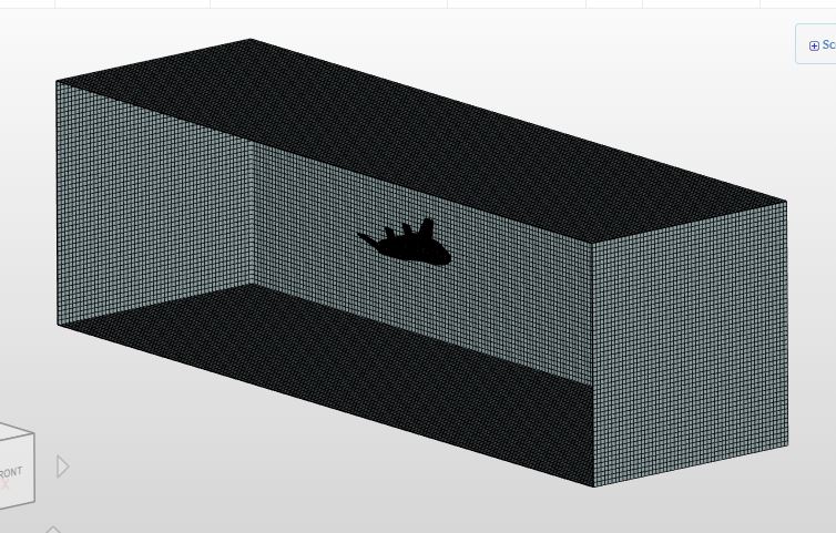
When I look at the Post-Processing results, all I see is a big blue square, the velocities at the outside of the fluid domain. The model at least ran completely because I made the fluid domain larger.
I need to see the aircraft surfaces, so I can see the pressures on the surfaces and the streamlines. I cannot see them because they are inside the big blue square. I tried adding a Contour Filter to cut out the box, but it only created a gray blob, although the box was gone. I was able to generate some image results that showed some information, although it was almost unreadable. I changed the display to points so you can just barely see the aircraft, although the streamlines are visible as solid curves.
Somehow, I need to hide the fluid domain (big blue square) so I can see the X-33 (aircraft). I need some help solving these problems.
Some general tips. First make sure to upload a watertight geometry, the one you used is still not watertight so we might see an improvement. On top of that you have to increase the size of your bounding box to make sure your boundaries are not influencing your flow around your body.
I don’t quite understand your solution. The problem I am having involves seeing the results, not getting more accurate results. I would like to see the aircraft as continuous surfaces with various colors showing pressures; plus, streamlines with many colors showing velocities, simultaneously in same image. I think I need to hide the fluid domain (big blue square, post-processing) so I can see the X-33 (aircraft) and streamlines (results). I need some help solving these problems.
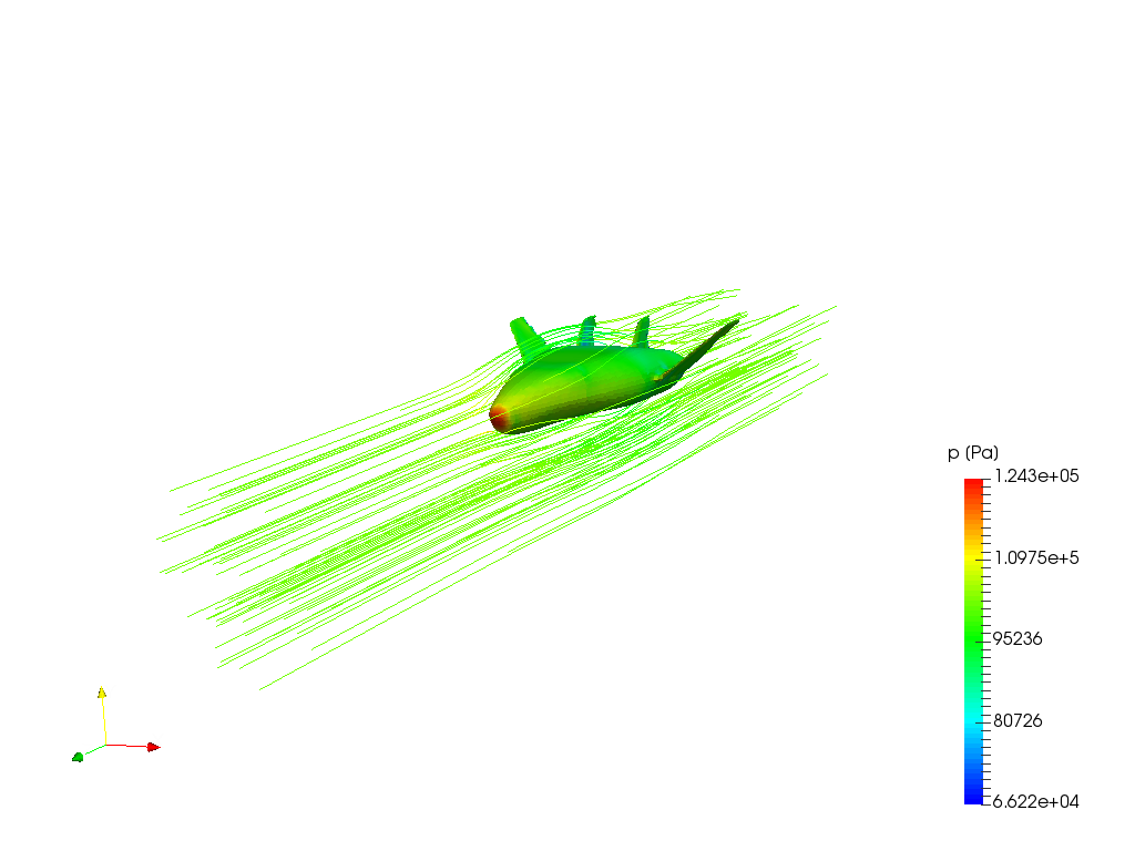
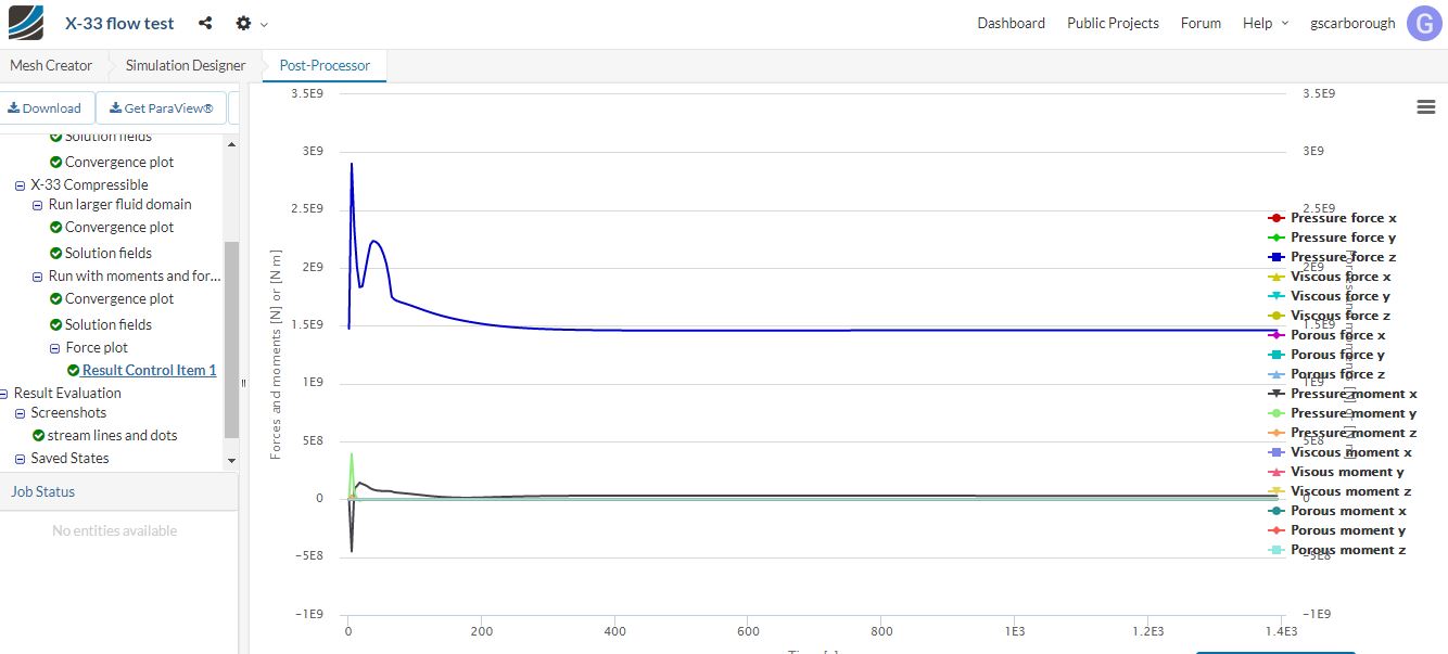
Created a new color picture of the X-33, showing reasonable pressure and streamlines results, although it looks a little scruffy (mesh very coarse). It shows the image of aircraft using surfaces with colors showing pressures; plus, streamlines with colors showing velocities. I could improve the results considerably by refining the mesh and creating an angle of attack that would show a more realistic aircraft environment, also picture quality. I also succeeded in creating a graph of the total forces and moments on vehicle required to determine the thrust for horizontal take-off.
I was trying to create an angle of attack for the aircraft to simulate aerodynamics of a takeoff. I could not rotate the aircraft (no CAD software, currently) so I rotated the direction of the velocity, instead. I am trying to calculate the lift and drag of the aircraft when it takes off and create nice pictures of aircraft with streamlines.
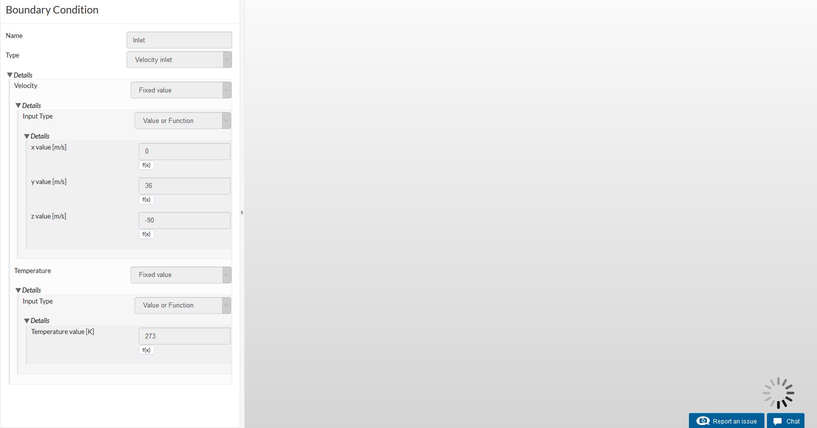
I tried to get a coefficient of lift by changing the Result Control Item. I changed the lift direction by making the y value of 1 m. I also changed the velocity at inlet (Boundary Condition) to have a diagonal direction:
Y value of +36 m/s Z value of -90 m/s
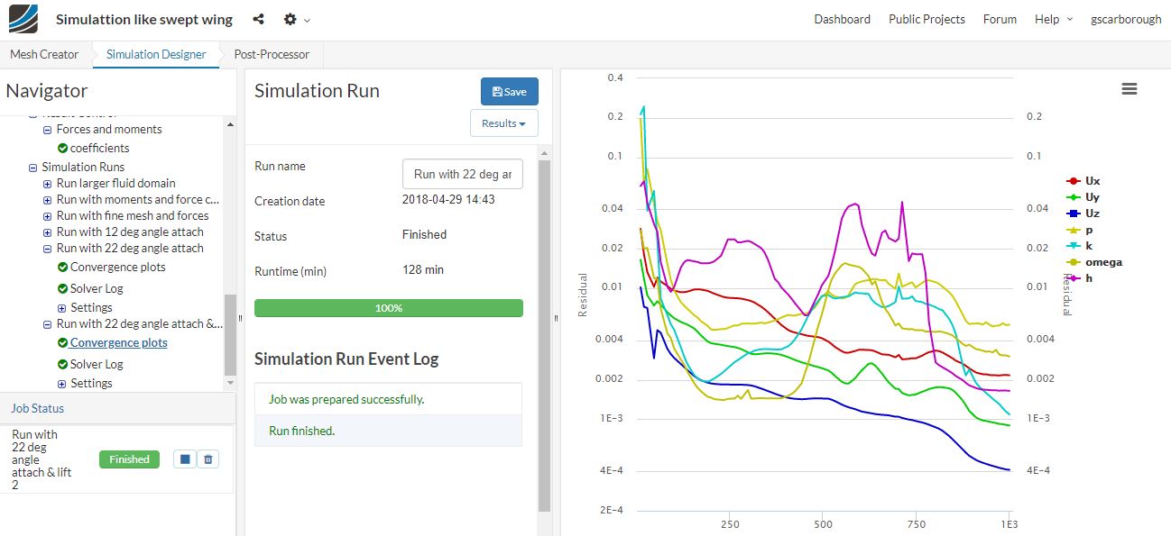
I looked at the conversion plot. it looks like the program could not find a solution to model. The average residual value is around .001, which I think is much too large. The swept wing project had a residual value of around .0001 and it generated a Solution field, plus nice force coefficient plots and Pressure Contour plot at root of airfoil. I used the Same Result Control Item properties of this project: lift direction, Y value = 1.
I thought I was getting pretty close to generating some nice model solution pictures (streamlines and pressures), as well as, determining how much lift and drag of aircraft, with a large angle of attack of twenty-two degrees. I think everything was going fairly well until I tried adding the plot of the coefficient of lift. I need some help solving these problems.
I would like to point out your model (x-33 full-body) is not watertight and this may cause significant instability due to the solver not knowing the difference between fluid domains and may produce inaccurate results. If you have time you should clean up the CAD model and ensure that it is free of defects before commencing meshing.
For your simulation, is it necessary to use compressible flow? What is the Mach no of the simulation? I would say anything less than say M 0.7 will not require you to use compressible flow as incompressible flow would yield sufficiently accurate results and give you less problems in stability and convergence.
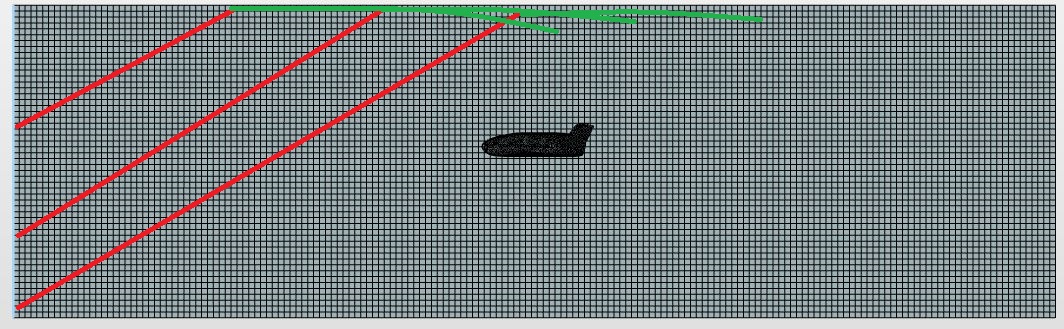
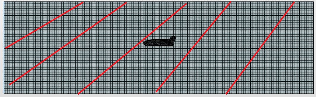
Orientation of the airflow like what you’ve done is a way to adjust the AOA of the aircraft but not in the way you have done it. You need to assign the entire vertical domain (front, top, bottom and back) as a single inlet-oulet in order accurately provide the AOA to the aircraft via velocity. The first figure is a visual representation of what is happening (excuse the janky drawing). As you can see the flow is not behaving like you want, you want it be like the second figure and that will then give you the AOA effect you desire.
Still can’t seem to access my latest project anymore.
I tried double clicking on “Simulattion like swept wing” project several times and all I got was:
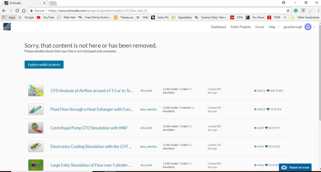
Sorry, that content is not here or has been removed.
Please double check that your link is not mistyped and complete.
The hyperlink you showed in forum is to my “Simulattion like swept wing project” that shows mesh and simulation information for both the 737 (twin jet airliner) and X-33 (SSTO aircraft), but solution results only for X-33. When I am in the Dash Board, hyperlink:
and I select the above mentioned project, I open up “explore public project” webpage with the following message “Sorry, that content is not here or has been removed” with hyperlink:
So, I am not sure which webpage and hyperlink you are trying to investigate. Those are the links and pages I have been working with, including my current project hyperlink as mentioned:
I have also been having trouble with other information required to define model:
Details unknown for my X-33 model, but used in 737 and swept wing projects:
Model: 737 swept wing
k: 8 .00375
Omega: 52 3.375
737 model only: Turbulent thermal diffusivity = 0
Results Control Items for swept wing that are equal to 1:
Lift direction (Y), Freestream velocity, Reference length, Reference area
Center of rotation (X) = .0003 all others equal 0
I have been using the information mostly from the 737 model, but I have no clue what to use for the Results Control Items, for my X-33 model. Also, what is “h” that is used in the Convergence plots mean?
The Model initial conditions (previous projects) where disorganized in other message, so resending
737 model
k: 8
Omega: 52
swept wing model
k: .00375
Omega: 3.375
Can you help me get my project working (open up). Also, give me the correct information so I can continue to refine my X-33 project to get more accurate and reliable solution results.
For me it does definitely not work! Could you create a new project please and share it with us? That would be the easiest way to make some progress here.


 I got what you mean. Is it okay if I post a detailed solution of the problem later on? Hope that’s fine!