In one of my past posts we already explored what is Sweep Meshing and how it can be utilized to produce higher quality meshes.
The Sweep Mesh approach is limited by the fact that the start and the end face of a sweepable body should perfectly match in order the sweep to be successful. Only a single pair of start-end faces is allowed per sweepable body.
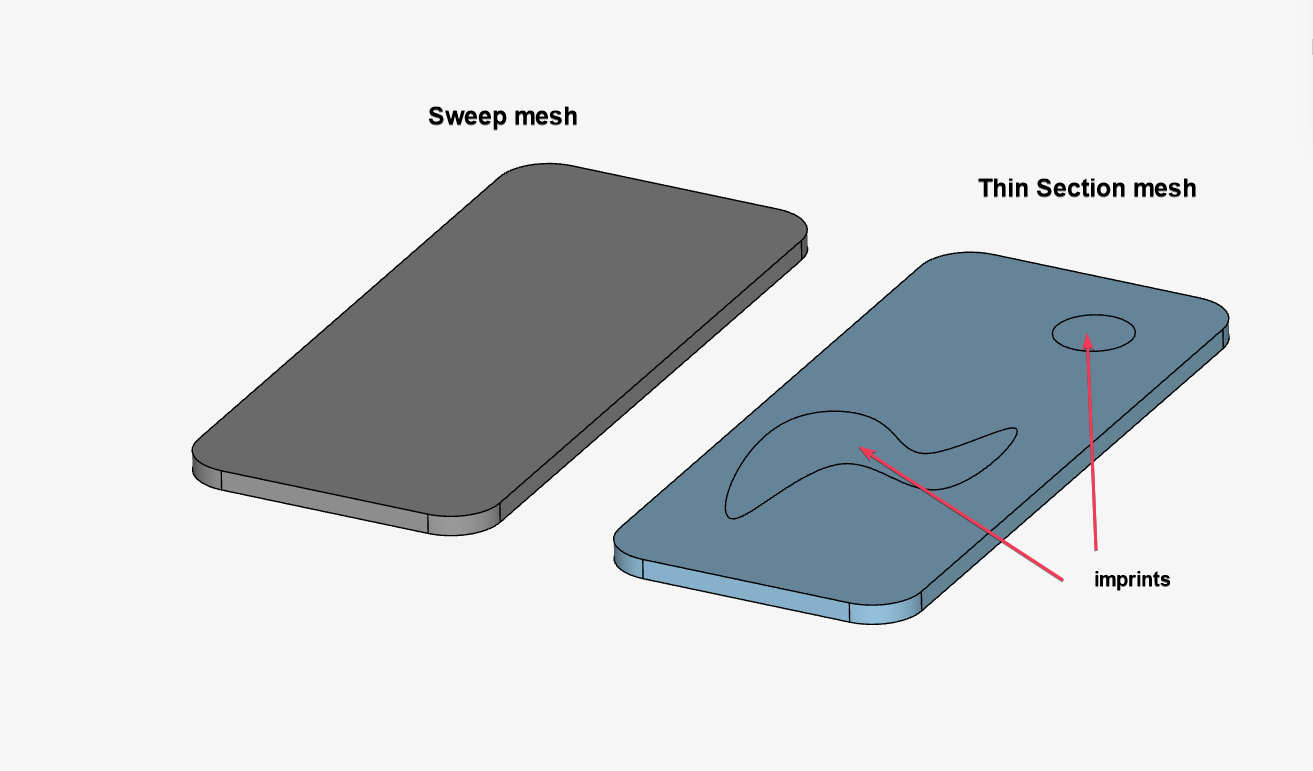
However, there are cases where a body might look sweepable, but the above requirements are not satisfied as there might be several sub-faces on one of the two start-end sides. A typical example of this could be a PCB where normally a lot of smaller electronic components sit on top of it. This approach requires several faces to be imprinted on top of the PCB preventing us from using the Sweep Mesh technique.
SimScale has recently introduced a variant of Sweep meshing, called Thin Section Meshing particularly useful for such cases.
In the following simple example we can see a thin plate with imprints which is an ideal candidate for Thin Section Mesh.
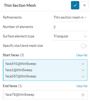
Using the Thin Section mesh refinement, we can now specify an uneven number of start vs end faces.
This leads to a nicely swept mesh through the thin section. The shape of the imprints is respected throughout the thickness and it is nicely transferred to the end face.
Feel free to check this public project example to learn more about our Thin Section mesh control.