Dear SimScalers,
in this weeks spotlight we will have a look at a simulation of a Dual Stage Thermoelectric Plate by our user @buzzing_info .
Dual stage thermoelectric (peltier) temperature control plate. Objective is -40°C plate temperature with 12°C chiller water. The simulations are testing the effects of different plate designs, materials and thicknesses, temperature sensor placement, as well as estimating \Delta T_{max}.
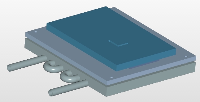
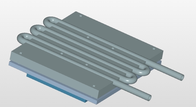
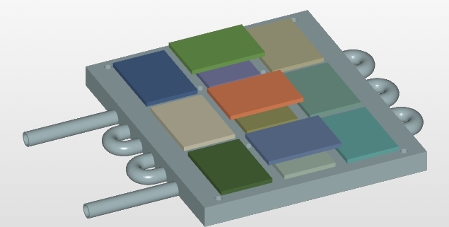
Geometry:
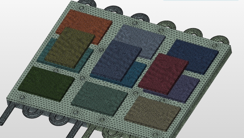
Mesh:
The complete internal flow domain was meshed using the ‘Tet-Dominant’ on the SimScale platform. The resulting mesh ( flow domain only ) consists of approximately 0.4 million cells and is shown in the figure below.


Simulation Setup:
The thermoelectric devices are simulated as a negative thermal flux on the top surface (the Qc, or cooling power), and a positive flux on the bottom surface (Qh, the hot side power, sum of Qc and Qe, the electric power in). Peltier devices loose efficiency the greater the temperature differential between the sides, this is simulated by setting the thermal conductivity so Qc is conducted completely through at \Delta T_{max} (the maximum temperature difference).
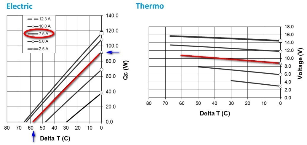
We’ll run them at 8$V$, since that’s more efficient than the maximum rated 12$V$ (thus less waste heat to be transported by the second stage). From the plots in the manufacturer’s datasheet, that draws ~7.5$A$ (and Qe = 8$V$ x 7.5$A$ = 60$W$), has a maximum Qc of 93W, and \Delta T_{max} of 58C. The device surface area is 0.00175 m^2, and thickness is 0.003 m.
From the Laird PC12,139,F1,3550,TA,W6 Thermoelectric Datasheet
Thermoelectric parameters in the model:
Top Surface Flux = - Qc / A = -93 / 0.00175 = 53143 W/m^2
Bottom Layer Flux = (Qc + Qe) / A = (93 + 60) / 0.00175 = 87429 W/m^2
Conductivity = Top Flux * Thickness / \Delta T_{max} = 53143 * 0.003 / 58 = 2.75 W/(m K)
Water Exchange Cold Plates
First type uses a single Aavid Thermalloy 416101U00000G water chilled cold plate. The second type (R1) uses 2 Lytron CP15G01 cold plates in order to get lower thermal resistance from the water to the thermoelectrics. This improves total \Delta T_{max} by ~5-10°C. Most simulations were run by setting a boundary condition holding the copper pipes to the water temperature of 12°C (285K), to visualize hot and cold spots.
Since energy transfer to the flowing water in the pipes was not taken into account, a better \Delta T_{max} estimation comes from the “BottomT Ctrl” simulations, which set the back of the cold plates to 12C, and set the thermal conductivity using the manufacturer’s data sheets, similar to the calculation for the thermoelectric device conductivity. The CP15G01 datasheet resistance from water to cooling surface is 0.009 C/W, or a conductivity of 111 W/C.
Plate Conductivity = (Thickness / Area) * Conductivity = 0.008 / (.095 * 0.15 ) * 111 = 62 W/(m K)
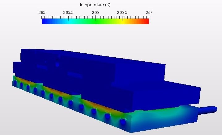
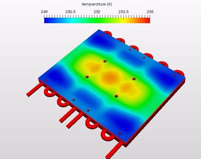
Results:
Final performance (assuming a normal convective heat load on the cooling plate surface) is \Delta T_{max} = 71K, or a minimum temperature of -59°C. The water bath will get up to ~20°C. This is similar to direct calculations. Also important is that reaching -40°C is simulated to take just 3 minutes from 25°C. Building it from copper instead of aluminum provides relatively little advantage. A critical factor in actual performance will be limiting thermal losses through hardware and surrounding structures.
SimScale project:
To look at the simulation setup, please have a look at the project from @buzzing_info :
Dual Stage Thermoelectric Plate
To copy this project into your workspace, simply follow the instruction given in the picture below.

\underline{\textbf{Visit our SimWiki by clicking on the picture}}