Surface Edge Pre-Selection Feature

I would like a feature that allows me to pre-select all the surface edges that I want to be followed precisely in the generated mesh.

Its just that only the tet algorithm seems to keep surface edges defined in a mesh. For all the hex algorithms and with features such as a sharp or thin trailing edge on a wing, you have to really ‘up’ the mesh fineness to avoid a jaggy mesh of the trailing edge (on an elliptical planform wing). If only I could just pre-select the edges of the trailing edge ‘surface edges’ that have to be precisely represented in the mesh and all other edges could ‘disappear’ with the algorithms face creation routines.

Surface Refinements appear to act on all edges of a selected face, I would like to be able to select individual edges of the face. And besides, surface refinements increase the number of faces locally near all the face edges whereas I think that by simply requiring a mesh to follow specific edges without increasing the number of faces along the edge could help improve simulation results without a large increase in faces near the selected edges.

I would think this feature would have to be useful for more areas of CFD meshing than just my simple example.

Dale

Thanks a ton for your feedback @DaleKramer!

Let’s see how many people are interested in this feature and we will prioritize accordingly.

Enjoy your weekend!

Jousef

Here is a good example of why this feature is needed.

I have a wing with ribs geometry.

I want to have my leading and trailing edges well defined in the mesh.

I do not need the ribs well defined in the mesh, in fact I would like them to blend in.

If I could have a refinement that let me select surface edges I would be happy but this is the best I can do so far (using Feature Refinement):

Smooth Geometry:

Bad mesh:

Hi @DaleKramer, @jousefm,

Yep great feedback, I agree it would be awesome, and have experienced the same issue in the past when I did a wind turbine project.

A workaround to this in case your interested, and it helps you now, is to split the surface of your geometry in your CAD system at the leading and trailing edges, and assigning a high-level surface refinement to it works well, all bar the extra effort.

Cheers,
Darren

Thanks, the geometry is already split there :upside_down_face:

I have used Surface Refinement with Hex Dominant Auto Algorithm but I believe I experienced the same issues, I will check again.

P.S. Very interesting topic you had on the your wind turbine, I have it bookmarked

And I ran out of votes before I could vote on some of the GREAT features you requested…

1 Like

Hi @DaleKramer, yes, I myself have also run out of votes :sweat_smile: but thanks for reading them, and feel free to add your own comments and input, hopefully, they will be valuable when it comes to implementing them.

Cheers :slight_smile: I wrote it when I first started, but still use it to remember how to do certain things.

Odd, did you delete the feature refinement and just run with surface refinements?

Kind regards,
Darren

It looks like my memory failed me a bit on this but I still have some EDGE jaggies (more noticeable on tip taper surfaces, @1318980 here is a project link if you want to help get rid of the jaggies from Mesh 5 :grinning:) which is 1/2 of what this topic is currently about.

Here is Hex Parametric Surface Refinement to same levels as Feature refinement of above (Yeah, the ribs are blended :slight_smile:);

So I can have a better view can you just highlight the split faces on the leading and trailing edges? And upload an image?

Cheers,
Darren

Like this:

Even better I added project link in Post 7 for you.

But here you go:
BetterSurfaceRefineMi1Ma6-ZOOMED

I am sure the planform and thickness taper ratios are aggravating the issue but it SHOULD handle it better.

I am thinking I need to delve into some parameters…UGHHHH…

Awesome, I’ll get back to you.

I just shared a project with you @DaleKramer, hopefully this will be a good starting point for you :slight_smile:

Best,
Darren

1 Like

Darren @1318980 ,

Many thanks for creating a starting point mesh with what, I assume, are acceptable current practices.

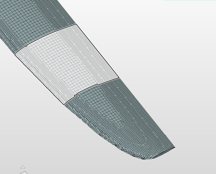
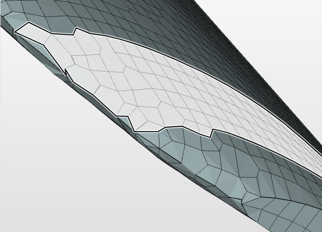
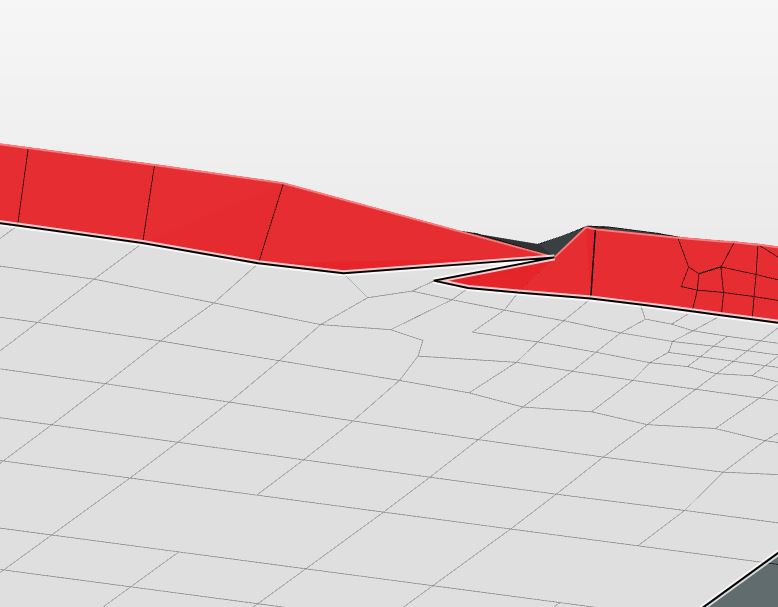
I have gone over your mesh, and I see that you split the top and bottom geometry surfaces near the leading edge so that you could mesh using level 8 only near the leading edge to reduce cell count and to try to ‘fix’ an algorithm shortcomming . Your mesh has about 683k faces. If I simply remesh Mesh 5 with the Surface refinement max level set to 8, I get an 850k mesh. so you are saving faces, but mine puts more refinement in the TrailingEdge and my Leading edge looks like yours. You have this in your trailing edge, my 850k mesh does not, I am not sure why.:

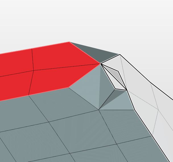
Another problem we both have is the trailing edge at the wing tip, this is really weird:

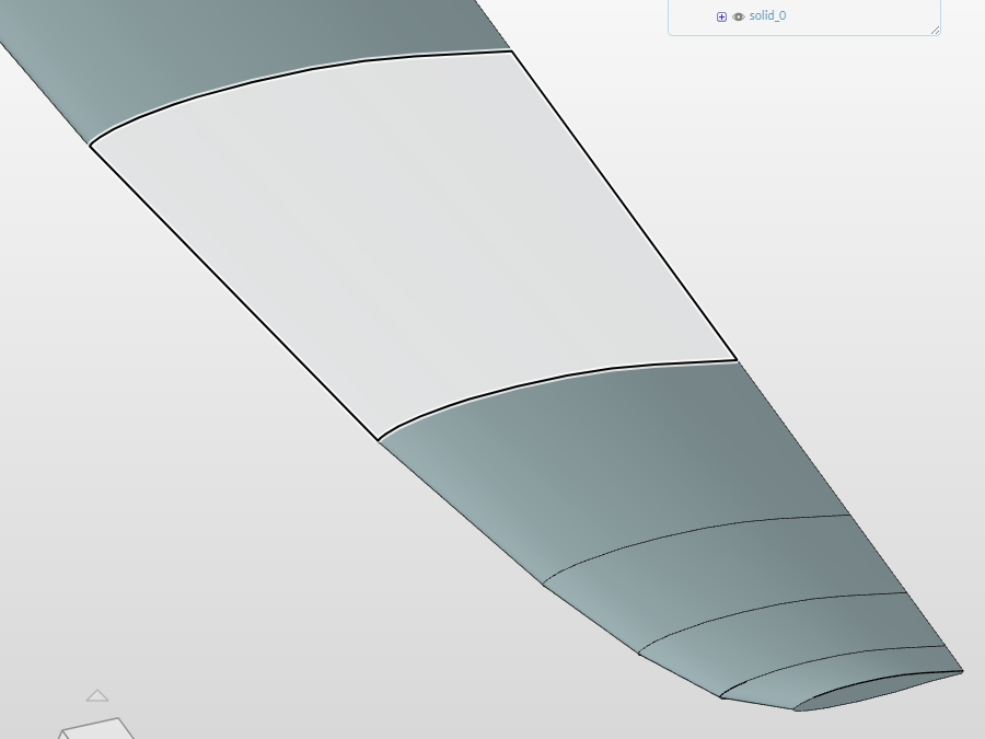
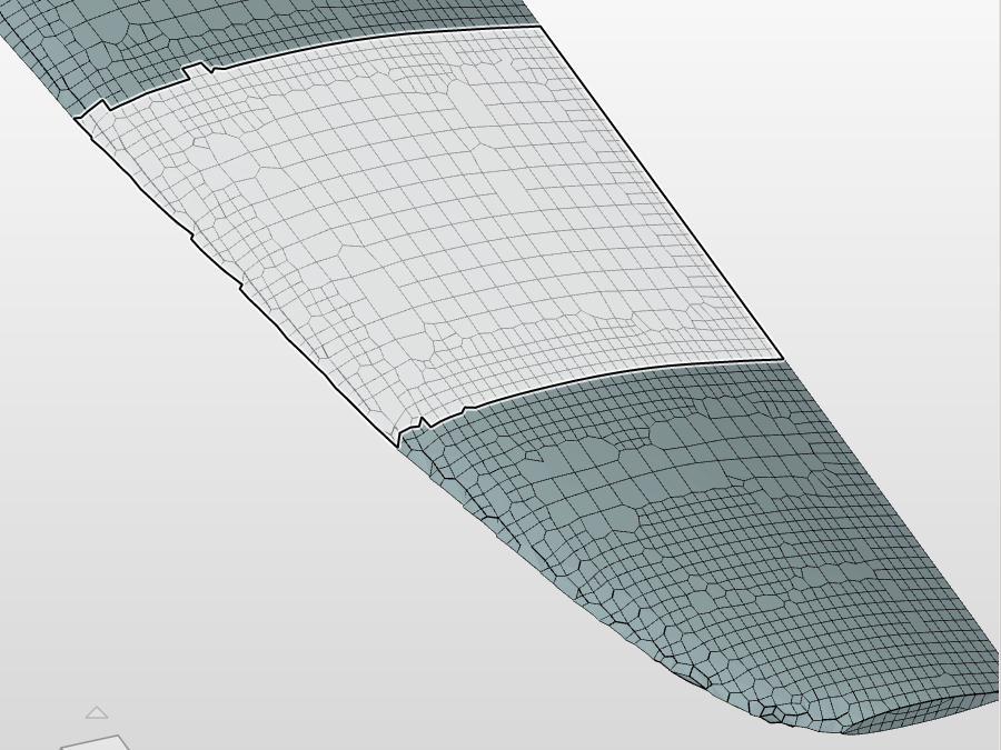
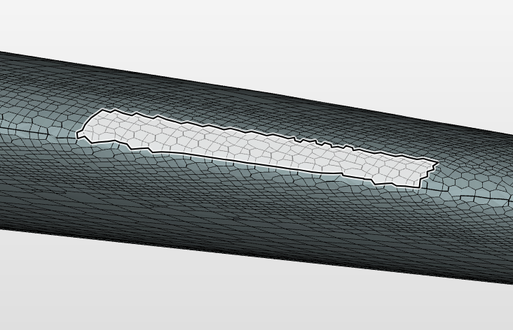
The thing is, if the algorithms that are suppose to be keeping Surface Edge definitions intact in the generated meshes, actually did just that, both of the above ‘messy’ areas would not exist. And, even in the level 8 leading edge meshes, the surfaces DO NOT follow the defined edges in the geometry as in this picture near the tip in your mesh (still not the straight lines of the geometry in that highlighted surface):

We would not need to go to level 8 and higher meshes if the algorithms just followed the edges we want them to (we could save lots of core time :smile:) .

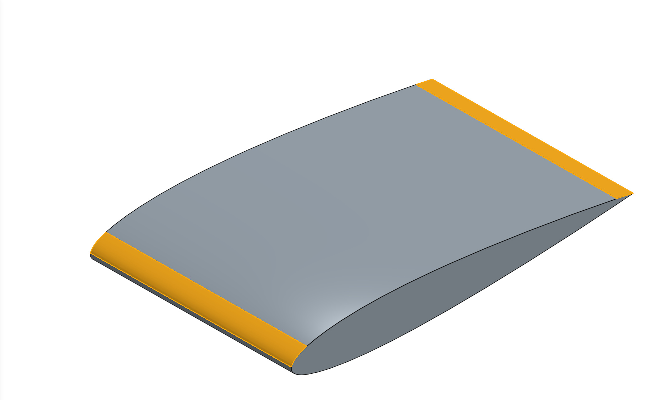
Also, I am not a fan of adding any more surface edges in CAD models than absolutely necessary, especially to overcome a shortcoming in a meshing algorithm. I almost cried when I had to split the wing surface at the leading edge to try to get the leading edge absolutely defined in the mesh by using the existing refinement algorithms that are suppose to keep edges defined…

I have been making CAD models for complex 3D printing for quite some time now and to me it is always better to design parts with fewer control points, surfaces and edges, lower degree surfaces, and fewer surface isocurves. In my experience this results in the smoothest meshing for printing.

In any case even at level 8 on the leading edge, the surface edges are still not defined precisely and I am blaming it on the algorithm not doing what I think it should do and I believe that there is no reason for it NOT to do what is expected of it. Sorry for tone, just getting a little frustrated :upside_down_face:

I will soldier on…

P.S. I am allowed to use up to 96 cores at a time, is there any reason not to do that?

Hi @DaleKramer,

Just to jump in quickly on this. 96 cores is a product feature of SimScale and allowing any free user to use such computing capabilities without paying a substantial fee would not be sustainable in the long run.

But I am allowed so should I use 96 all the time, or is there a longer queue time to wait for 96 to become available and it is only worth it for long runs. It looks like to me a lot of the time on short runs is not core time and I do not notice much difference between 32 and 96 in real time.

Hi Dale!

More cores does not always mean faster. Maybe this video from us can help you understanding the concept a bit better:

Best,

Jousef

2 Likes

@jousefm

Great info, bookmarked, thanks

But it only implies that because all these cores have to talk to each other, all jobs use less core hours with fewer parallel cores used, real time may be longer but cores hour are less. Am I correct?

Hi @DaleKramer,
if parallelization would be “optimal” - double the cores would mean half the computation time. So in an ideal scenario the total core hours used would stay constant and only the real time should vary.

In reality, due to a number of reasons (the scaling is usually good only in a certain range of the ratio “number cells/core”, not all operations being parallelized, hard disc I/O restrictions, limited network throughput, pre- and post-processing of raw result data,…) this is not the case.

In a good scenario you can get up to ~90% end-to-end parallel efficiency (usually long computations where the pre- and post-processing steps are negligible).

For all these reasons, we aim to completely free the user from the headaches of choosing the optimal parameters and instead of selecting the number of cores, let them just choose if they want the an “economic” setup (meaning lowest core hours spending possible), a “fast” setup (fastest possible run time, or a “custom” setup (for the ones that want to do some performance comparisons, or similar).

Best,
Richard

I understand those vagaries of parallel cores, but in any case, the least number of man-hours (core hours) to dig that hole in your video is when 1 man (core) digs the hole, so I think the answer to my question should be Yes.

If so, I should just leave a simulation run at 1 core and go to sleep for the night and minimize my core time… :smile:

I am glad of your effort to make it easier to decide how many cores to use when I am rushed for time.

Nice idea Dale but it’s not that simple unfortunately :wink:

The system can run out of memory if the number of cores is too low.

  • 8 cores for intermediate mesh sizes (2-3 million cells)
  • 16 cores for large meshes (4-5 million cells)
  • 32 cores for very large meshes (6 million cells and onwards)

Best,

Jousef

Wow, that is counter-intuitive… I guess I need to find another job :wink: