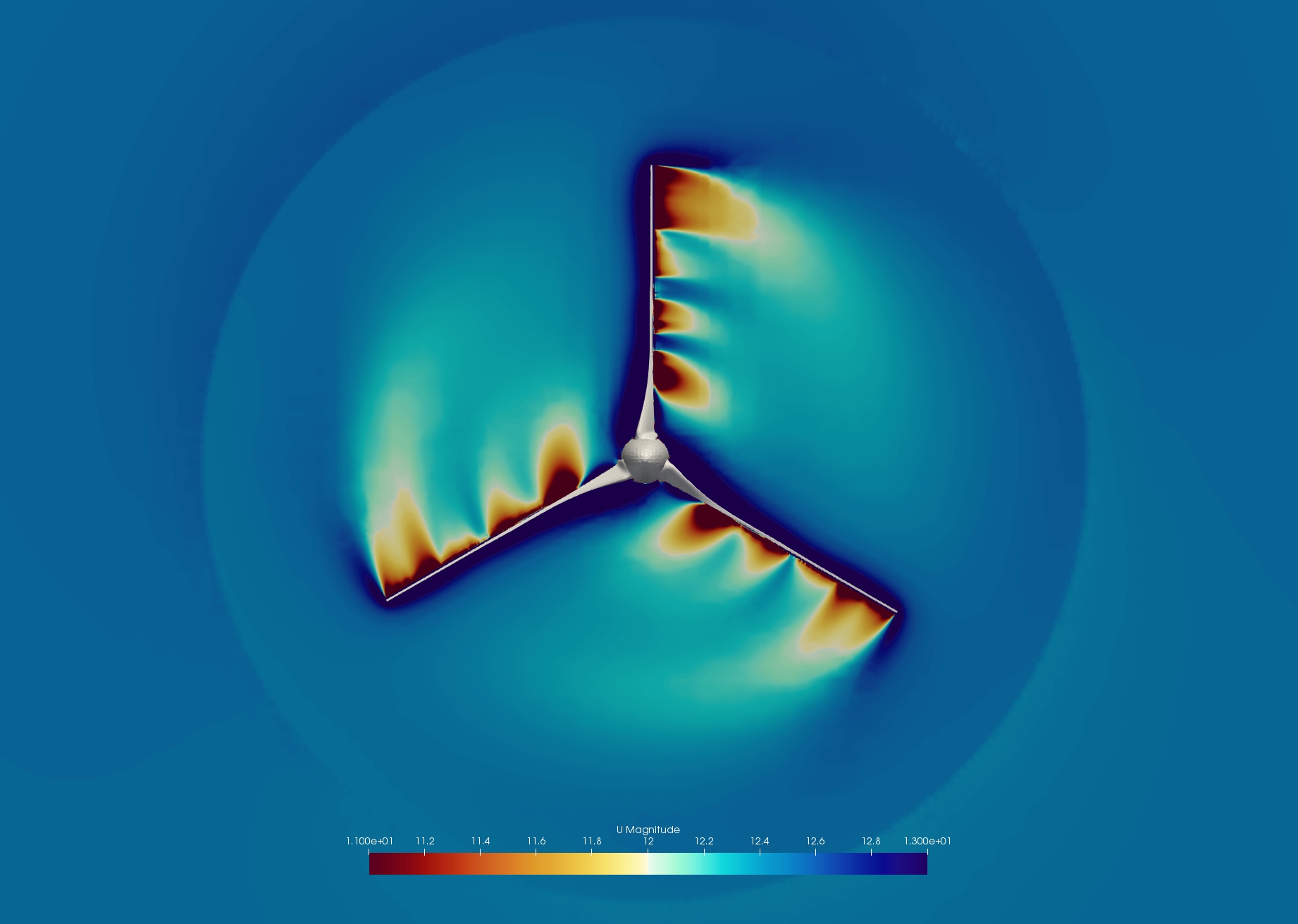
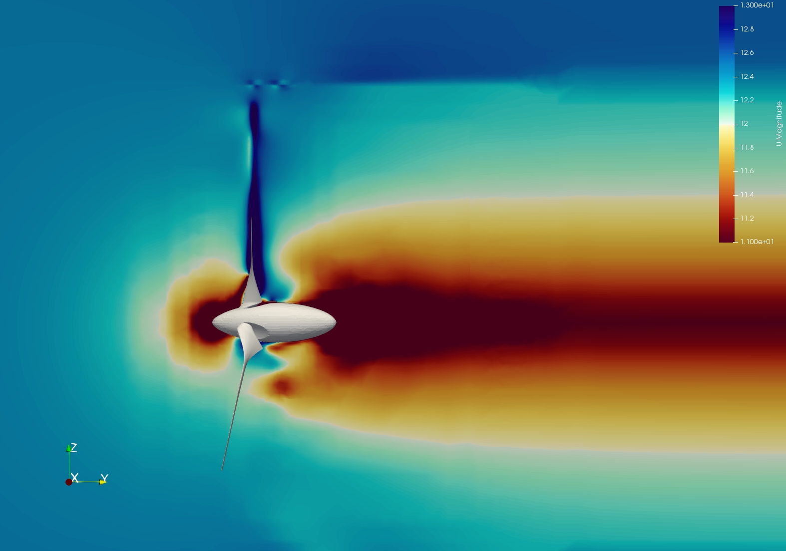
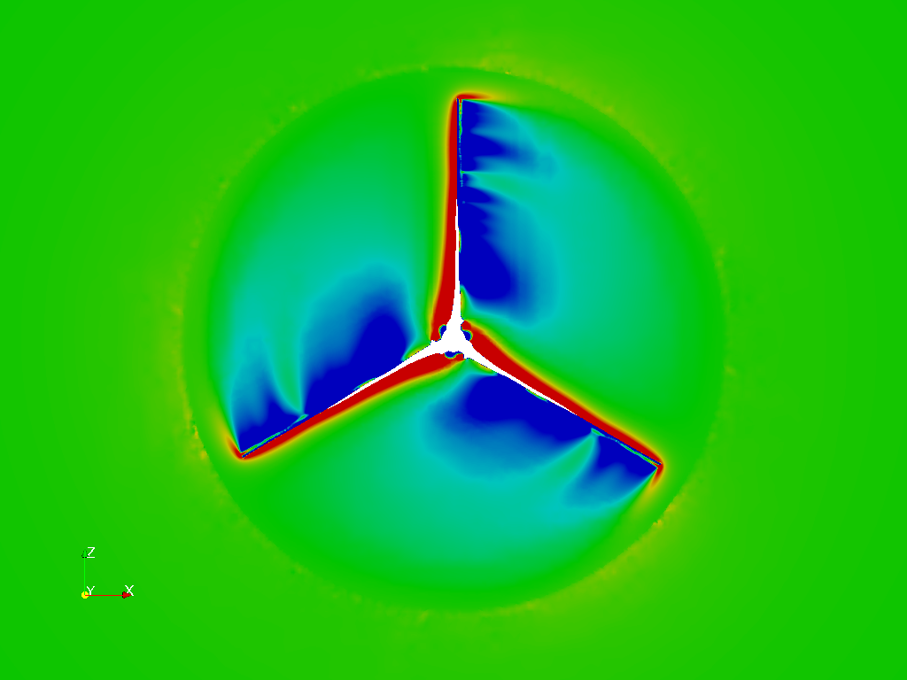
Hi, I’m having troubles with MRF and results. It appears that the MRF is interfering with my Wind turbine design, it looks like the fluid isn’t allowed to enter or escape through the side. Looking at the image above you can see this with the faint ring. it is more noticeable here:
I don’t recall having this problem before, is this expected behaviour? if so what recommendations are there to improve results? keep expanding the MRF region?
for starters, all the tips have different velocity profiles and the top blade has different results to the other two. My cad is now rotating around the y axis going through the origin (as defined in my MRF setup) however it still looks like the issue has something to do with this.
I’m a little stuck with this so open to any suggestions. I resolved my old geometry to ensure that that works as expected, which it does so it doesn’t appear to be SimScale side.
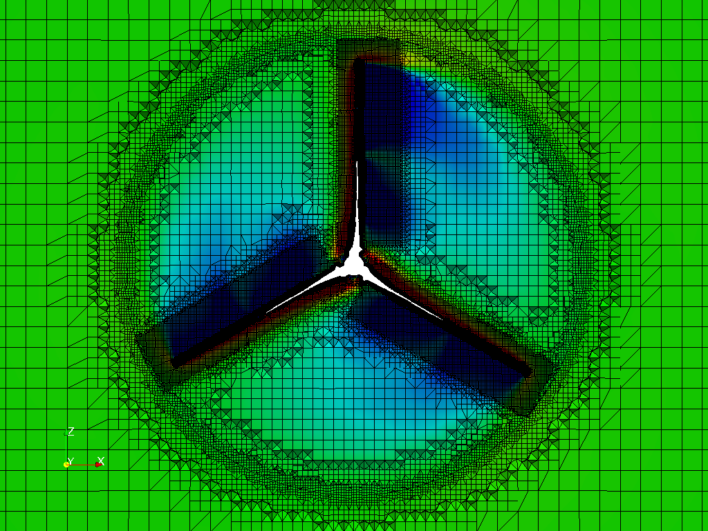
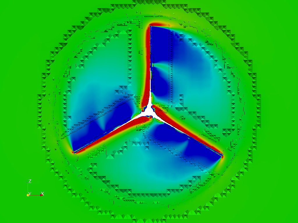
@1318980 the mesh looks ok at the first glimpse. Are you sure you did not introduce any mesh error in the AMI interface as well as on the blades? In an incompressible simulation, a poor quality mesh can create nonphysically high local velocity in and near the bad cell. Can you check this with “Treshold”?
Second thing, how tight is your convergence? Did you check only residuals, or did you have a look at lift/drag evolution, or a pressure probe near and far field? Did they converge as well?
Convergence was good, it went to 1e-5 on all residuals and forces and moments were steady from very early in the simulation. I will look at the mesh quality in a bit however I cant see how different geometries could all mesh with poor quality cells always at the tip of blade 1. I’ll get back to you, many thanks!
Darren, meshing will not be rotational symmetric because of the cartesian background mesh. So upper vertical blade will experience different snapping than the lower two that are rotated. However, adequate resolution usually resolves this problem so that the mesh, although different, should not necessarily be worse than on the other blades. Did you mesh it with “Allow free standing zones” option? Without that I usually get better MRF interfaces