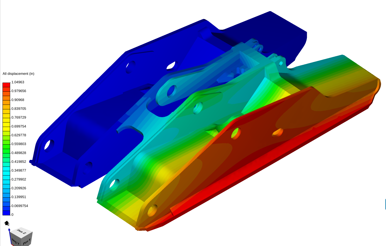
This project is a static simulation of part of a roof support machine for underground mining. The part is the base of a machine like a giant heavy-duty scissor jack. I am trying to see of the large plates that tie the two halves of this base together are adequate. These two ‘bridge’ plates are colored orange and purple in the model.
The mine floor is very uneven at times, so I am trying to simulate one base stuck to the floor and the other one suspended and held up by the linkage it is attached to and the two bridge plates.
I am model, mesh, material, everything fine, just the simulation won’t run.
I get the message: "An error occurred in the resolution of the contact constraints. At least one contact definition is superfluous since all its slave nodes are already constrained by other contacts or constraints. Please review your simulation setup."
Don’t know what this may be. The error message would help a lot more if I knew what was superfluous in the contsraints or nodes.
this error typically happens if a plate is constrained on both sides AND the top face with contacts. I agree that the error message isn’t incredibly helpful in this case and should be improved. For the time being: Running an Imprint operation before you simulate the model helps here, as it only “bonds” the parts of 2 plates that really touch to each other.
Thanks for the tip. I am still having trouble on my end. Whereas before the model would mesh but not calculate right, now when I load the STP file, do the imprint, it won’t mesh. I chased down a couple problem areas but the FACE that won’t mesh is not a face in my CAD…it is an edge.
Tried it a bunch of times now and just not meshing. Maybe some sort of setting on my end because I get different results than you on the same geometry?
Will forward this to my colleague who will reach out to you as soon as the issue has been investigated! Try the other mesher in the meantime and let us know if that solved the problem!
Hello Again Simscale:
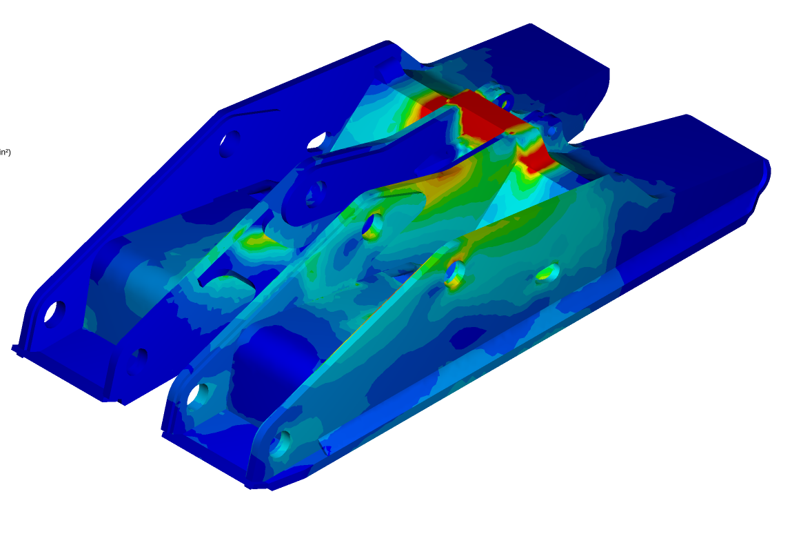
Over the weekend I was able to get some simulations to finish. If you look at the project I have made a bunch of attempts to make it work and get some reasonable results. One thing that keeps happening is a result that I know just cannot be true. If you go to the simulation solution field below and look at total deflection…there is an orange area right next to a yellow area. These two plates are welded together, and in fact I have combined them into one item in my CAD package. So they should move together as one. Also in general the deflections seem to be really small when compared to what I actually see in real parts.
Sorry, I can’t add much here as to how to make your simulation match your known deflections in a real part, but I just have to comment on this somewhat typical Computer Aided Design Analysis (CADA) experience that you are having now…
Over my brief (1 year) experience with SimScale and the areas of CADA which SimScale encompasses, I have come to the opinion that most CADA results are not very reliable UNLESS the simulation results have been proven to match experimental results closely. To achieve this, it takes a LOT of expert knowledge in the particular facet of CADA that you are investigating in order to setup a valid simulation, and to be able to use those results with confidence. Once you have matched experimental results, then and only then do you expose the true, game changing, benefits of using CADA. By that I mean, now you can vary the geometry slightly or the boundary conditions of the simulation and you can then expect those new results to be close to what you can expect if you made those changes in the real life object.
Thanks Dale. I think you are very right. I have always said it seems like folks that bring in FEA data and pretty pictures can make it look however they want, depending on motivations. It is a useful tool though if you are just looking to compare some ideas as long as it isn’t to crazy in assumptions.
I do see though that maybe there are some problems in the units of the static simscale simulation. I had been using SI units and I think there are some major unit problems when you go that direction. In fact if you look at deflections, I think the resulting number in Inches is the same as if it was in Meters. So I was looking at 0.023 inches when I redid it in Metric and the measurement is 0.023 Meters. So I think the program is handling pounds and Newtons correctly but not the length in the total deflection graph.
I thought, how hard can it be to simply convert them properly in the SimScale interface?
It turned out, that answer was, very hard, and I know they tried.
My solution was to forget all about English units, I advise you not to question this but to adopt only SI units here at SimScale (even in your CAD files…)
You should be able to search and see my forum posts about this (~1 year ago) …
I know you will get there on your results, don’t give up, good luck…
It is fortunate that you have real life results to look at…
Hi @petersing,
the reason you see the two parts acting as they were not connected is that actually are not connected by any bonded contact.
You can check if a face takes part in any contact by selecting it and select “Filter contacts by selection” from the context menu: Selection Tools (Tips & Tricks) | SimScale Knowledge Base
Hi @petersing,
I wanted to quickly inform you that indeed we found an inconsistency in the scaling of the mesh for the solve step for your US customary units project. We are already working on a fix and will release it ASAP.
In the meantime, you can switch to the “New mesh preview” mesher, which does not suffer from this issue.
In any case I will inform you once the issue is resolved!