Hi @jousefm !
i started my mesh operation and got an error, so i started a new operation with the exact setting, wich i got above.
now i have the same error again and cant start the mesh operation.
Sorry for the late response @rizzo!
Do you want to share the project with me or did you already solve the issue by yourself?
Best,
Jousef
Lingering Question…
From the first session, my results showed the pressure forces on the two designs to be essentially equal. Since I didn’t expect that, I thought I must have used the same wing model, so I carefully re-ran the mesh and model getting essentially the same results.
My questions are:
- The pressure forces seem to be equal for both wings. Why?
- Is it because both wing designs are in a stall or near stall condition, so the high down-force wing is very little different from the standard wing?
Comparison chart, from second run:
FORMULA CAR FRONT WING DATA
Standard Px Pz Py
Flap 25.55 -25.80
Wing 9.00 -94.25 -8.15
High Down Force
Flap 25.57 -25.85
Wing 9.02 -94.16 -8.14
Original run: https://www.simscale.com/workbench?publiclink=4ee6ed90-70df-4b1a-aee3-c57ecf51de70
Second run: https://www.simscale.com/workbench?publiclink=24332b99-6fdc-4278-8e2a-eea267dee93f
- One other item: is the viscous force the drag? If not, what is the significance of the viscous force x?
i know the similarity may be academic at this point, but it still makes me wonder why. Can anyone explain it?
Thanks,
Don
Hi @dond,
Thank you for the question, I’ll answer as best as I can.
- Pressure forces are not the same. You have to be careful what you look at because the main wing is the same for both setups, what we are changing is the flap angle. If you look at the force plots for the main wing they’re going to be the same in both cases. But if you look at the flap force plots, you will see that the pressure force in X is 25N for the high downforce setup and 22N for the standard setup.
- The first standard setup is not near stall, if you look at the post processing you will see that in the standard setup there is no flow separation behind the flap, but there is flow separation for the high-downforce setup.
a. What does this mean? That at this velocity, the high downforce setup is actually less efficient than the standard one. This flow separation means a less effective wing setup and thus leads to the fact that pressure forces in Z are actually bigger for the standard wing (i.e it generates more downforce because flow doesn’t separate). - In this case the viscous force doesn’t represent the drag. It is a component, but its magnitude is insignificant when compared to the pressure forces in X (where most of your drag comes from).
a. Viscous drag comes from viscous forces that act parallel to the surfaces and come from the shear stress between the fluid and the surfaces.
b. Pressure forces act perpendicular to the surfaces. In the case of drag it’s related to the cross section perpendicular to the flow. In this case you have a pressure buildup on the forward facing faces of the wing and a pressure drop on the rear facing faces - this results in drag. Also, you have faster flow under the wing (which leads to a pressure drop perpendicular to the wing) and slower flow over it (which leads to a pressure rise) which leads to a resultant force in the z direction that you know as downforce.
c. The more you streamline a body and reduce it’s cross section in the direction perpendicular to the flow, the viscous forces will become more prominent than the pressure forces.
Thank you for the excellent and detailed response.
I forgot that the wing and flap are treated separately.
Again, thanks
Don
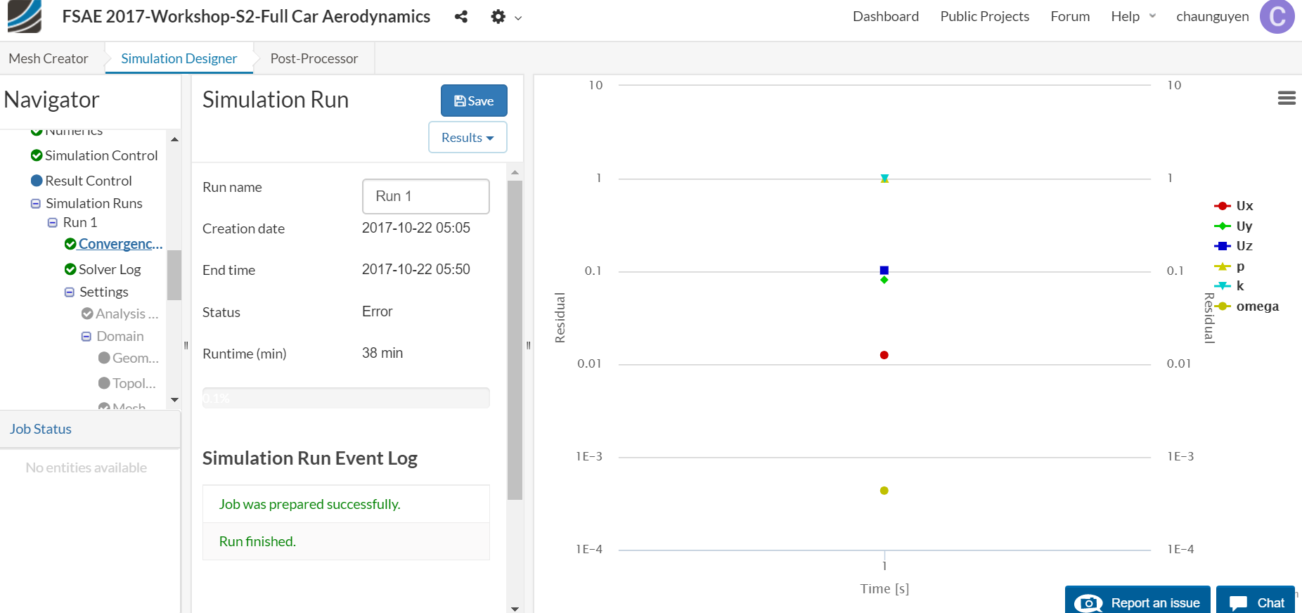
Hi @chaunguyen!
I ran the simulation with increased number of CPUs as well as an increased runtime. Convergence plot looks “good” now. Shared the finished simulation run with you. 
Best!
Jousef
Hello,
I am facing problems while simulating for the tutorial 2. I have tried multiple times but simulations always ended up with the same error. I havent used the porous media & rotating zones because i am unable to create close surfaces required to create volume. I have tried to open the same tutorial model in Catia but it shows unsupported. I have also tried to open in Onshape but it was not successful, error was translation failed.
My project link:
Any suggestion to get rid of simulation error, merging surfaces for the STL file will be much appreciated.
Thank you so much in advance.
Regards,
Kartik
Hi Kartik!
The problem is that you have still some bad cells inside of your mesh, make sure that the structures called “Barre” are meshed with an increased refinement and then look at the meshing log if you could reduce the number of erroneous cells.
Best,
Jousef
Hi Jousefm,
Thank you so much for your quick reply. I will try it today and update it for the same.
Regards,
Kartik
I just have a quick question with regards to Exercise #2: Full Car Analysis in the Applications of CFD in Formula Student & Formula SAE course. I’ve currently spent a while trying to mesh the car, but unfortunately, I am constantly met with an error in the event log detailing an error with a cell zone. After doing some research and looking through the forums trying to rectify this issue, I realised that the cell zones can only be created using volumes, but “MRF_F”, “MRF_R” and “Radiator” are all deemed faces in the model and when trying to select volumes, the entire model “solid_0” is only selected. I have tried altering the model in Exercise 2 using SolidWorks and noticed that the model was seen as one entire solid rather than sub-elements, which is reflected in the STL file, as the 2.5 million lines were encased between the one volume. I decided to try using the Exercise 3- full model and noticed that the model was also treated as a single volume. I downloaded it and noticed that the STL file is separated into the various sections. I disassembled the STL file and followed the 2 processes in STL file compilation found in the Exercise 4 pdf. Unfortunately, when loading the newly altered STL file into the exercise, ensuring the MRF zones and radiator are volume entities, they still appear to register as faces. I’ve tried resolving this by also following the various forums which have alluded to the same thing, but haven’t been able to fix the issue. Do you have any suggestions, as I’ve tried converting the MRF sections to volumes in order to create the cell zones, but have had no success, even though I have
tried altering the model and STL files?
I’d greatly appreciate any suggestions!
Thanks in advance!
Hey @gdonegan,
There was a change in how porous zones are selected (only volumes are allowed now). Please take a look at this detailed discussion. By the time this workshop went live, face selection was possible but not anymore.
/Ric
Hey, i am stuck here with this problem - “A cell zone has been defined with assignments of faces. This is not supported. Please create a closed solid region that exactly represents your cell zone in your CAD tool.”
Have tried selecting the volume tool first but it does not fix the problem. Can you please suggest me what to do?
Thanks
Hey,
Cell zones have to be a volume (separate to the flow region). Make sure to have a look at this tutorial, that makes use of a MRF rotating zone: Fluid Flow Through Centrifugal Pump | Tutorial | Simscale
Figure 22 is of special interest:
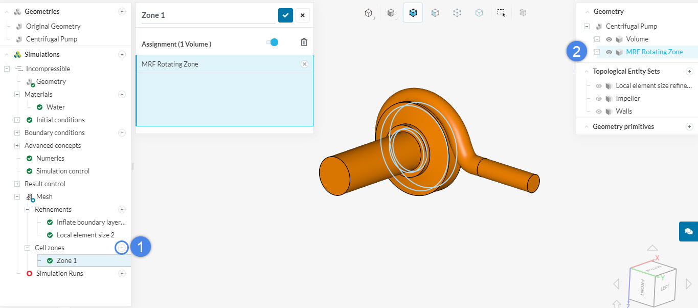
If you’re still having issues, make sure to post your project link so we can have a look!
Hello Ricardo,
Thanks for the support to the user ‘bbari’, I am facing exactly the same issue he had faced, I can understand that MRF and the Porous Medium should be in Seperate Volumes and not as a Surface, but I am not sure how to ungroup the MRF’s and Radiator from the Solid assembly.
Can you please help me with this, below is the link of my project
https://www.simscale.com/workbench/?pid=5522997268464954680&mi=spec%3A728bc4ab-1050-49cb-9f51-4ec40120f0ff%2Cservice%3AMESHING%2Cstrategy%3A1117&sh=1116
Hey there!
Please have a look at this topic for more insights. But long story short, the model has some faulty surfaces, which are making it get flagged as a sheet body. Once the faulty parts are fixed and everything is a solid, you should be good to go!
Check this simplified model to see the difference: https://www.simscale.com/workbench/?pid=1295674389835736516&mi=geometry%3A1&mt=GEOMETRY
Sounds like a great idea Thomas! ![]() Do you have any example in terms of CAD so we might give that a spin soon
Do you have any example in terms of CAD so we might give that a spin soon ![]()
Cheers!
Jousef