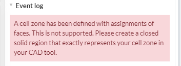
I am running a model of our potential car and am having some meshing issues. I can’t seem to be creating the cell zones as per the tutorial because it says the mesh zones are selected using faces. I have not had this problem before. How can I solve the error?
Hey @tinaalim,
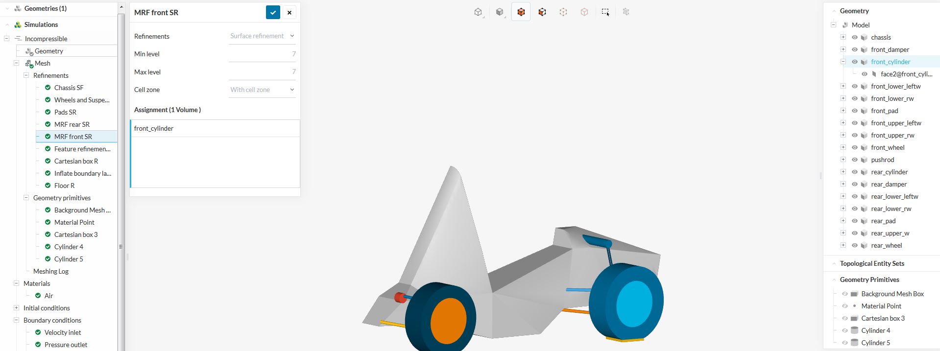
i have looked in your older simulations, and there i noticed the following.
The front_cylinder is a volume, and you pick it to mesh it with the cell zone.
@Kai_himself I have been having the same problem with MRF zones being picked up with a face selection and not a volume. How do you select a solid body so that it is recognized as a volume in simscale? I believe this will solve the MRF zone problem.
I haven’t done anything new in terms of how I have created the geometry for my selections to change. Do you have any idea why this has happened? Also, the webinar tutorial does the same thing as me and they are able to get results. why is that?
Webinar link: CFD in Formula Student and Formula SAE - Session 2: Complete Car Aerodynamics - YouTube
@ 1:07:44 mark
@tinaalim Simscale definitely changed something on their end so that MRF zones need to be selected as volumes and not faces. I have also been trying to get this resolved but havent gotten a response yet. Last year all MRF zone simulations were accepted with faces … now they are not.
But stl files turn everything into faces anyways, so I don’t know how to remedy this! I managed to get volumes on a previous geometry, but that was just sheer luck and not due to anything I had changed with creating the files or meshing them.
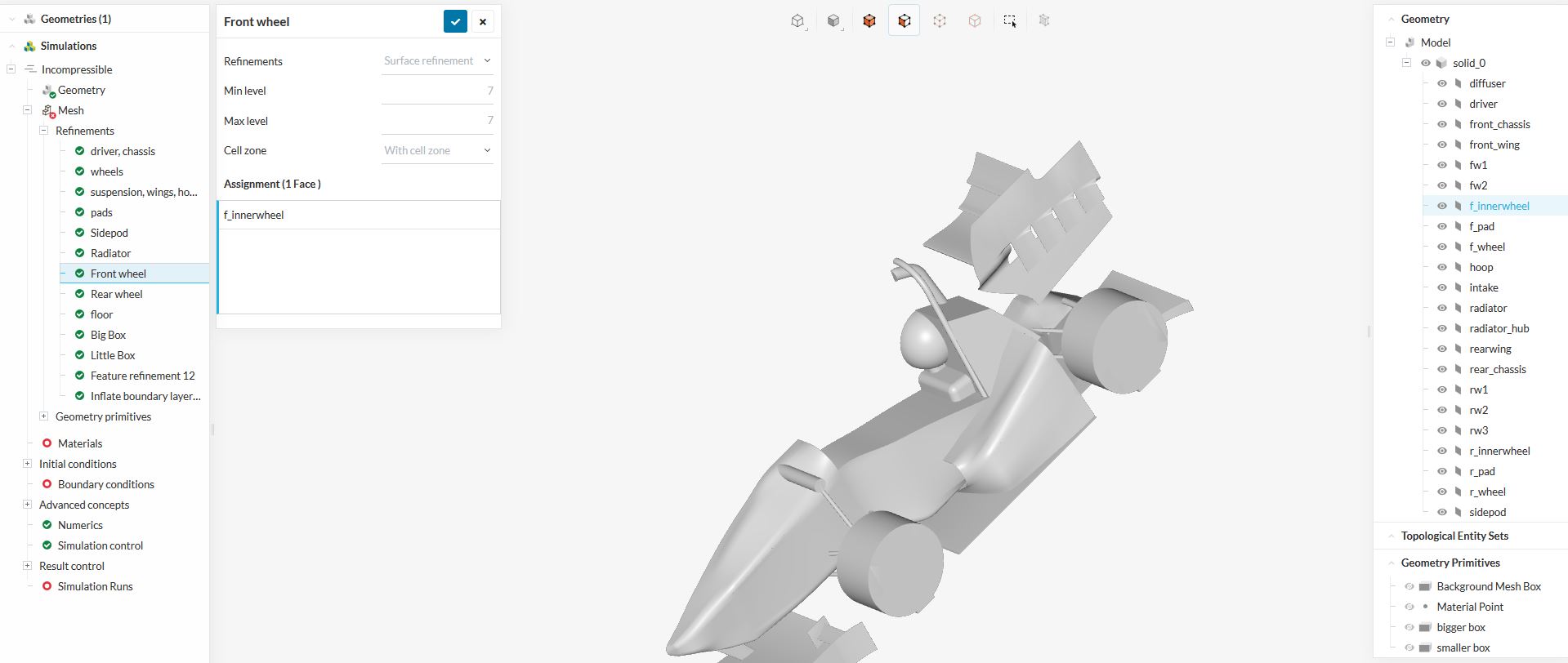
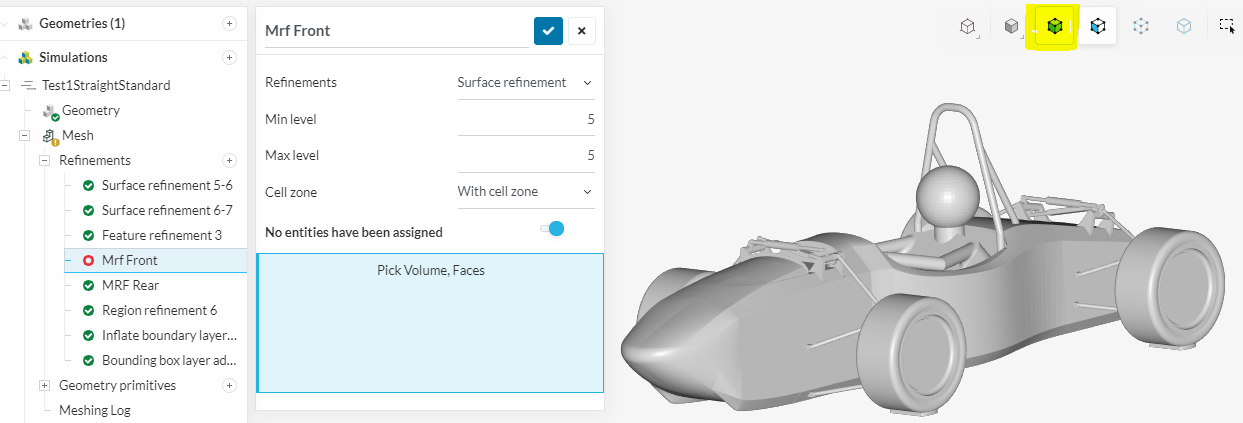
Yes I have been aware of this for quite a while. I think what everyone has been wanting to know is HOW to get a volume selection in simscale. When the STL is imported only solid bodies are created and when the MRF zone solid body is selected either in the tree pane or by clicking on the solid, it is always slected as a face.
I have also already tried to click on the “select volume” button on the top toolbar but this does not work.
Does the CAD Geometry need to be changed for it to be accepted as a volume?
Does the STL Data need to be changed?
Am i just not selecting the solid body correctly?
Any help would be appreciated. Maybe add screenshots for other users to follow.
We will soon release cell zones for the new standard mesher - you should then get rid of this problem. Regarding the volume selection you can share the project that is affected in your case and I will have a look at that.
I believe i have stumbled upon the answer to the volume question, although i wasnt attempting to solve it.
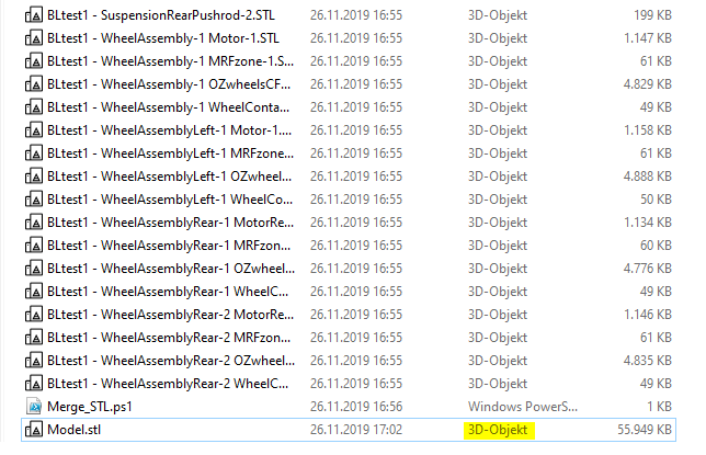
I was trying to do some quick meshing to see the effects of different boundy layer settings (i want to have a good representation of the Y+ value between 30 and 300) and i used the merging script provided by simscale as this saves a lot of time. The merging script just throws all the STLs together but creates a 3D object file as the output shown below.
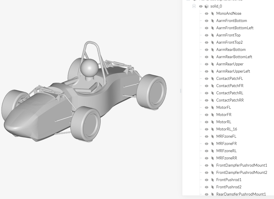
Normally i merge everything by hand in notepad so all files are saved as TXT files, which i believe converts the face selections to solid bodies. This is shown in the next picture where i merged everything manually and the drop down menu for each entity in the tree is now gone.
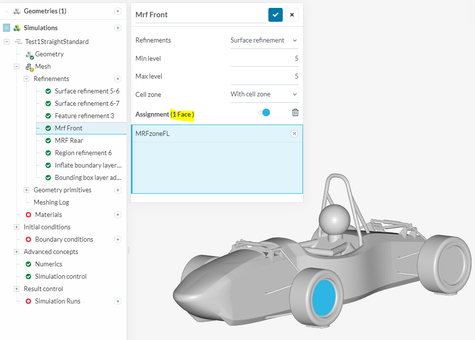
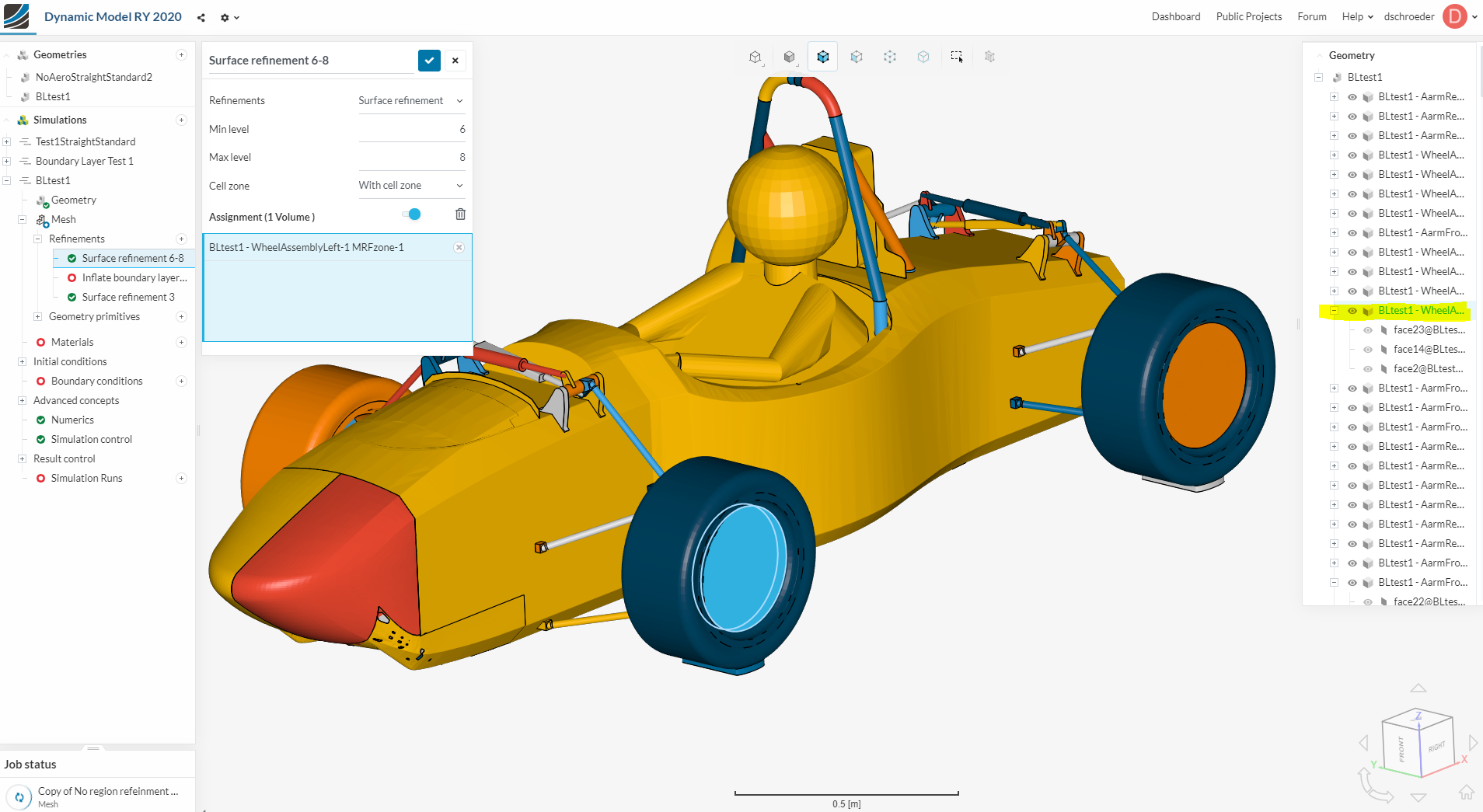
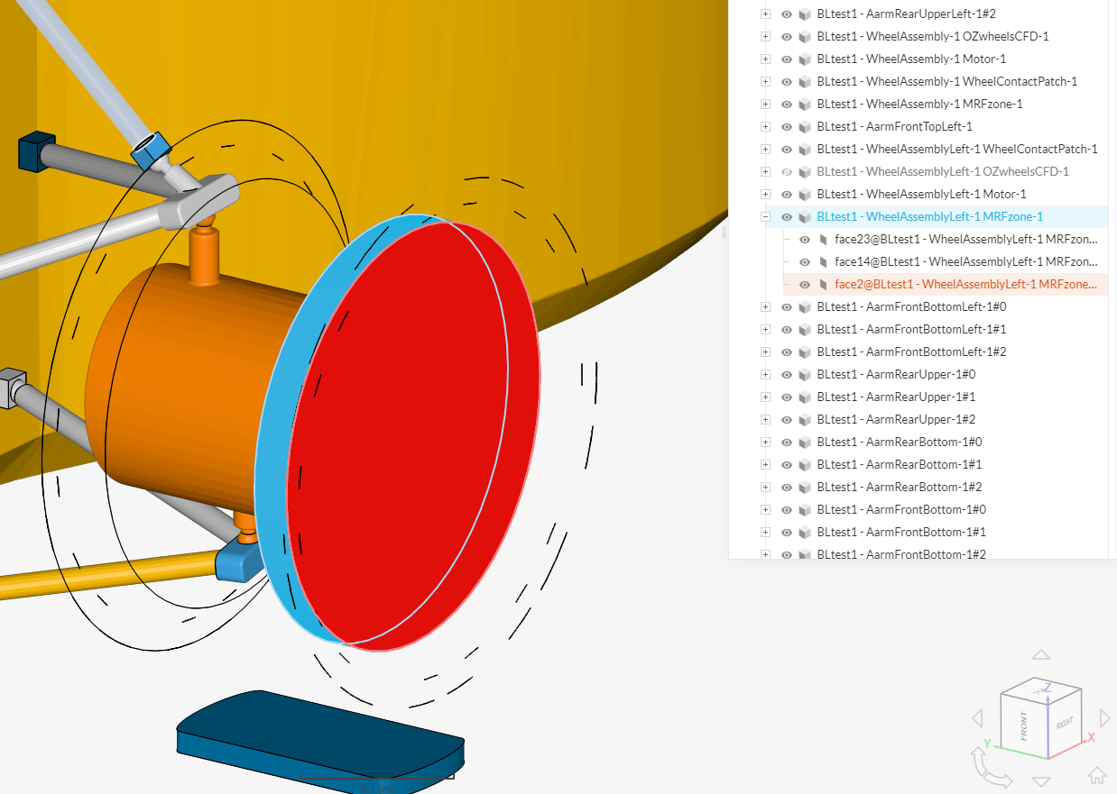
This can be seen under the highlighted MRF zone in the picture. This object is recognized as three faces, which, when combined are classified as a volume. This is shown in the next picture.
Would be very happy to know Dan - keep us updated.
Something we definitely changed is that cell zones are not allowed on sheet bodies anymore, so it needs to be a closed surface. (@tinaalim & @dschroeder)
My geometry includes closed surfaces and no sheet bodies, but the error is generated because the solver refuses to generate mesh zones using faces. What can I do?