Hi @chaunguyen!
Everything works perfectly fine! Please note that the simulation starts autonomously when creating a new one and loading in the post-processor might take a while. Can you try it again and tell me if it works for you?
Best,
Jousef
Hi @chaunguyen!
Everything works perfectly fine! Please note that the simulation starts autonomously when creating a new one and loading in the post-processor might take a while. Can you try it again and tell me if it works for you?
Best,
Jousef
Hi,
Somehow when I changed the maximum runtime from 8000 to 12000, it worked! Thanks for your help!
Best,
Chau Nguyen
Hi,
Can someone explain why there are boundingBoxes in simulation? I am trying to create my own mesh for other project. But when I go to Simulation, instead of having region0 which includes boundingBoxes and solid0, I only see solid0. So, I have nothing to select for my inlet, outlet… And for this project also, why there are no boundingBoxes in Mesh but there are in Simulation?
Although this is not very related to this workshop, I think it would help me a lot if I know where things come from.
The link to my other project is SimScale.
Thanks,
Chau
I just realized that the material point has to be outside. Everything is working fine now. Thank you!
Just wanted to answer  Glad you found out!
Best,
Jousef
hey can you help me to find where is the problem i have the same error but i can’t fix it
Hi @mostafanovek!
Which software are you using? Did you try downloading another model from a user, delete the frontwing and add yours with OnShape for instance?
Edit: Sorry but I see now that you are referring to the simulation errors and not a modelling error. Will see what I can do for you @mostafanovek! Getting back to you as soon as I know more.
Cheers!
Jousef
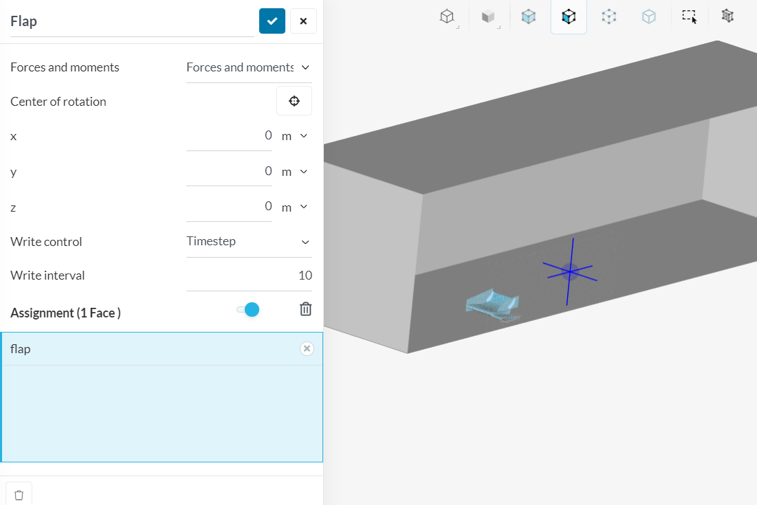
What is a center of rotation for the main wing? What does that mean? If I want to have my own wing simulated would I need to find out where the center of mass is?
Best regards,
Zaapex
Hi @Zaapex!
The point is the center of gravity. If it’s a uniform object it is the center point (like center of a sphere or rectangle etc.). For complicated structures one has to find it through some other techniques @yosukegb4, @pfernandez and @1318980 might give you more information about.
Best,
Jousef
Hi @Zaapex, you can do all sorts with the centre of rotation. If you set it to the centre of gravity you can see how much moments are created around it which might be useful for calculating forces on suspension, grip on roads etc. But there is no requirement as to where it is, it is just where you are calculating the moments around, it could be arbitrary if you need it to calculate the center of pressure or something or set to something more physically meaningful as mentioned above.
Hope this helps,
Darren
Hello,
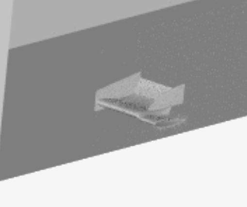
I am having a problem that after I meshed the standard wing, I dont have the same views as you guys. I cant see the solid_0_FWing and solid_o_flap. It seems that it all disappeared but I still have the mesh. Have a look at the photos. So when I try to select boundary conditions on the wing it looks like there is something wrong. Also when I am selecting the force moments. Looking forward to hearing from you.
Here is a link to my project with everything ready to simulate: https://www.simscale.com/workbench/?pid=3208119190490234883&mi=spec%3Af0eaee74-adce-4a44-9813-2c596d22bebb%2Cservice%3ASIMULATION%2Cstrategy%3A97&ps=analysis%2FIncompressible--oneOf%2FresultControl%2FforcesMoments%2F1
Here are photos:
@yosukegb4, can you help our user here please? ![]()
Hi @ThorkellH !
I added your ASCII SLT solid name after endsolid and upload the fixed STL data in my project at URL below.
solid FWing
...
endsolid FWing
solid flap
...
endsolid flap
Screenshot of fixed data
Does this solve your problem?
Best,
Yosuke
Hello!
Thank you for replying! This link only takes me back to my dashboard. Not sure what to do with it. I dont get access to your project if that was the intention.
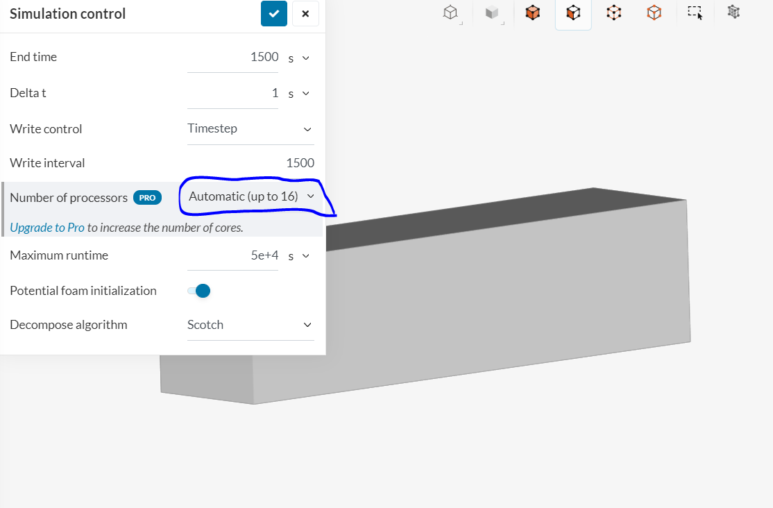
Looking forward to hearing from you. Another problem though, is that the running time exceeds the public community timelimit. I cannot change the number of proccessors in the simulation control. I can only choose automatic, up to 16 cores. See image below.
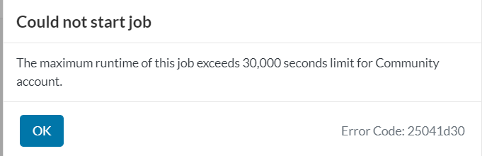
And this is the error I get:
Hi @ThorkellH ,
I’m sorry the project was private.
I changed the test project public.
And is another problem core hours issue? @jousefm
Best,
Yosuke
You can ask the @power_users to run the project for you or buy additional core hours - if you want to do the latter, feel free to get in touch with me.
Best,
Jousef
Hi @yosukegb4!
I would love to run your case, but can’t see the simulation saved in the project you shared.
Best regards,
Evgenii
thank you
Hello again Yosukegb4!
Thank you for you comment and access to your project with the upoaded STL data. It works better now but it is not perfect.
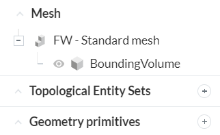
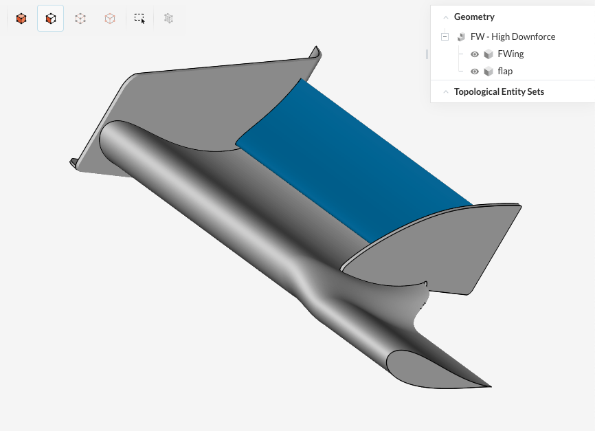
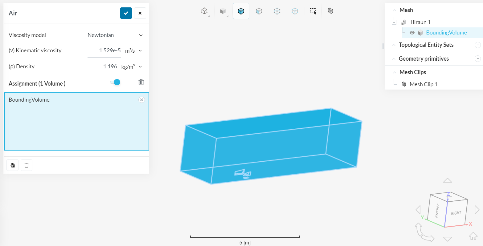
Now after I mesh it, and try to select air as the material I can only select the boundary volume. And it looks like the wing has become a part of the boundary volume. Does is still look okay? See image below:
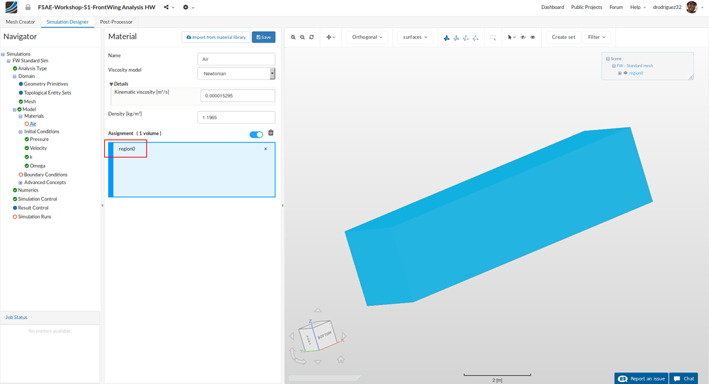
I get this bounding volume while you get an item called Region0 and it has access to the wing objects. The plus sign under region0 that opens those files up. Why do I not get the same access? I could still select the faces for the wall no-slip BC and force and moment calculations but I had to select them by hand. I could not select the main wing for an example with one click. I had to select all the faces of the main wing manually. Maybe that is okay, I’m not sure. I just don’t understand why I get different options.
Looking forward to hearing from you.