Is three element front wing allowed according to rules?
Thanks man! Fixed it for me!
you can change the units in catia V5 under tools-options-parameters-units to meter! after that i just saved the files as STL’s and merged them with the tool
1 Like
Gretings @frankpot
Thank you very much for your help, I have followed the steps that you gave me and I have finally assembled my wing with the car correctly, however, when I save the assembly as an stl file it only appears my wing in the file without the car, also, I tested uploading this file on Simscale and I get the error “Error during uploading file FSAE-Workshop-S4 Front Wing Design-Simulation.STL: HTTP 405 Method Not Allowed”, what could be wrong with my file?
Best regards.
sorry i should have mentioned that when you saved the assembly as STL only the wing will be saved. What you do next is the same as in the Step-by-step tutorial “Merging the STL files”. The wing will now be on the right position.
this worked like a charm… thank you very much.
Hey
My .stl file looks like this:
solid
facet normal +0.0000000E+00 +1.0000000E+00 +0.0000000E+00
outer loop
vertex -1.2762032E+00 +6.4799980E-01 +5.7774537E-02
vertex -1.4781550E+00 +6.4799980E-01 +1.7075706E-02
vertex -1.2921644E+00 +6.4799980E-01 +6.1525498E-02
endloop
endfacet
facet normal +0.0000000E+00 +1.0000000E+00 +0.0000000E+00
outer loop
vertex -1.6688230E+00 +6.4799980E-01 +6.3698818E-02
vertex -1.6692495E+00 +6.4799980E-01 +5.5626404E-02
vertex -1.6700000E+00 +6.4799980E-01 +5.9700000E-02
endloop
endfacet
.
.
.
facet normal -9.1935896E-01 +0.0000000E+00 +3.9341974E-01
outer loop
vertex -1.7179422E+00 +6.4799980E-01 +1.0342862E-01
vertex -1.7179422E+00 +6.5399980E-01 +1.0342862E-01
vertex -1.7195042E+00 +6.5399980E-01 +9.9778492E-02
endloop
endfacet
facet normal -9.9037126E-01 +0.0000000E+00 +1.3843686E-01
outer loop
vertex -1.7195042E+00 +6.4799980E-01 +9.9778492E-02
vertex -1.7195042E+00 +6.5399980E-01 +9.9778492E-02
vertex -1.7200539E+00 +6.5399980E-01 +9.5846422E-02
endloop
endfacet
endsolid
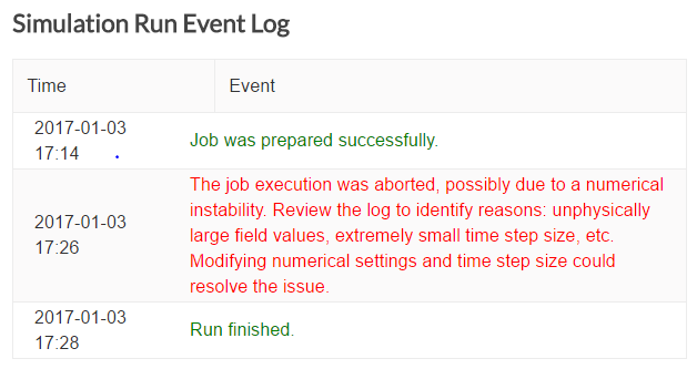
Seems a bit strange when compared to the examples and to some that I found on the internet. I uploaded it to simscale without any problems, but when I try to simulate it i get the error “The job execution was aborted, possibly due to a numerical instability. Review the log to identify reasons: unphysically large field values, extremely small time step size, etc. Modifying numerical settings and time step size could resolve the issue”
Anyone has any clue on how to solve it (think these error might be related to the format that the stl file was exported)
PS: Im using siemens nx10
Yes, you can use as many elements as you want. Just pay attention to the keep out zones.
Hello,
my simulation is unstable. I tried some different values in the simulation control such as the timestep but it didn’t work. In the second homework my values worked fine. Maybe anybody can help with the settings.
Regards
I have the same problem. Can’t merge the carmodel and my test wing together, Both methods are not working with my stl files.
Did u exported the .stl as text(ascii)?
However you can also upload just the wing to test if your cad is fine
@luiscalzado Yes I just tried that, My wing cad file is fine.
Did u managed to mesh and simulate it as well?
I see what you mean. I’m working with CATIA and saved only as “.stl”.
Without choosing STL ACII or Binary format. After searching for this options I haven’t found this options to save in other ways.
Greetings,
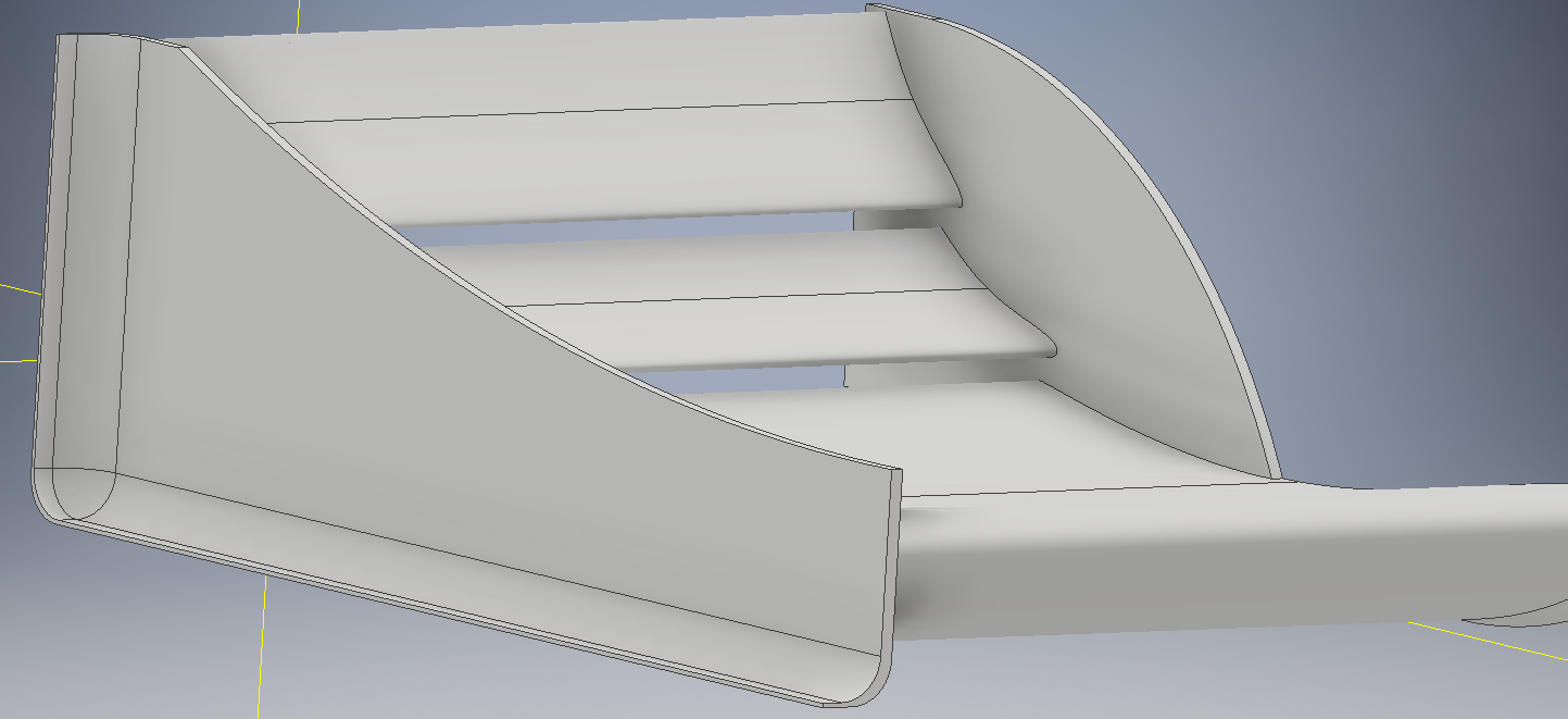
Right now I’m in this kind of a state (using CATIA for design):
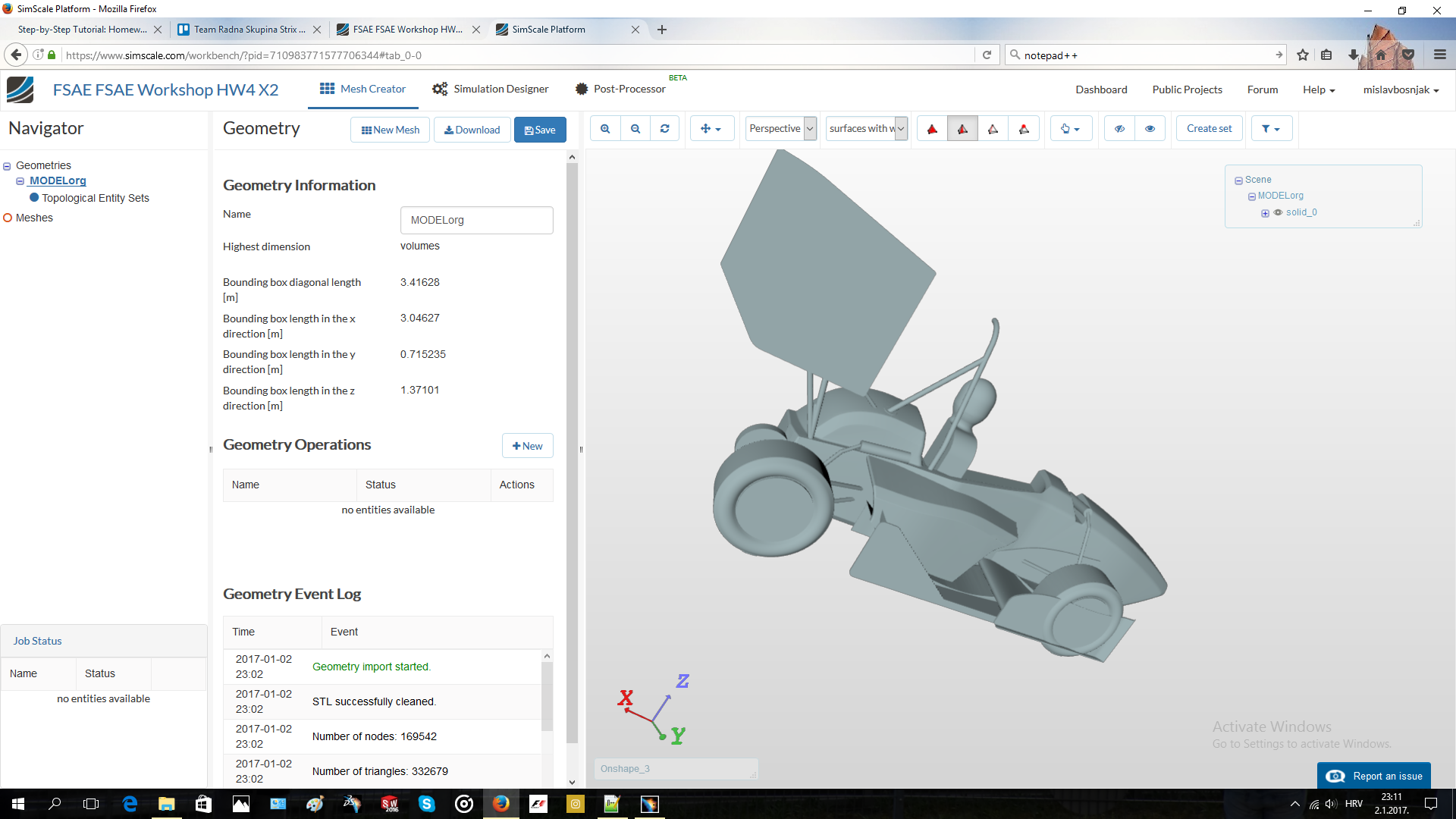
Clearly, the Front wing is not in the right position…
To solve this, I would have to adjust the wing in the assembly. For that I would need to upload the car model to on-shape, export it as step and then adjust the position in Catia. After that I need to follow the steps shown for the Notepad edit.
Is everything I’ve said correct?
Hi @mpayer,
I don’t know. Try to contact @pfernandez.
[solved]
I’m using Inventor17 for my CAD modeling. I have the issue that while exporting, the txt dokcument looks like this. Does anyone got a solution for this or do i have to use an other CAD-Programm.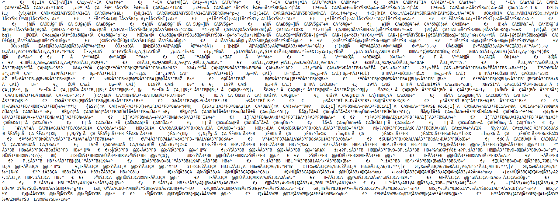
I found a solutuion i importet the files into blender an exportet them with ASCII code
[SOLVED]
Good morning SimScale team,
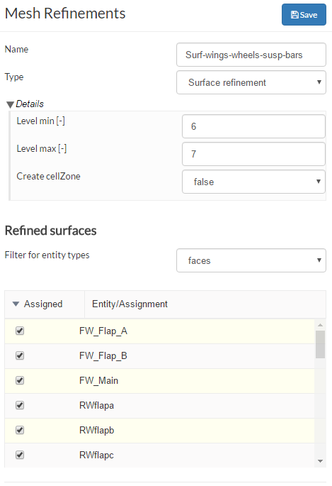
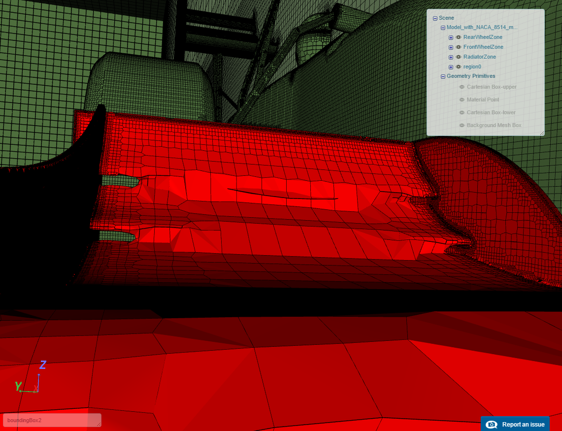
I’m currently trying to generate the mesh for my Formula SAE Front Wing (session 4 homework). It’s a three-element wing, and between the elements, the mesh is too coarse and doesn’t mesh the 12mm gaps correctly, as evidenced in the attached images. Which parameters should I modify in the mesh refinement? The current parameter values are also in the attached image.
I have also tried to change the Mesh refinement minimum and maximum to 9, but then I get an error in the Mesh generation. This is my project link, and any help generating the mesh would be appreciated.
Carlos Andres Prieto
University of the Andes, Bogotá Colombia.
EDIT: I solved my problem. The .stl files from the front wing all started with FW, and the mesh generator assumed it was only one body. I renamed them, and the mesh is now generated correctly. Thanks to user pfernandez.
1 Like