That would be my guess too, it will obviously be less realistic, but if the geometry is clean then it can be used with acceptable results from the sim.
Hi, How could i resolve this problem? I tried many configurations but everyone gives the same problem.
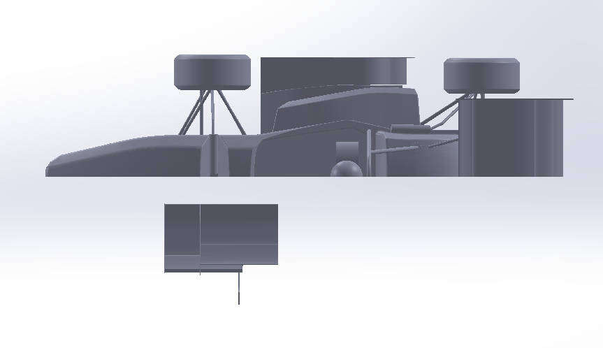
I used Solidworks 2016 to create Front Wing.
thank you.
Gianni
Hi @Gianni_S,
could not find your project in your Workspace. Is it on private? If the meshing log says that the meshing process has been finished without any errors you can proceed with the simulation.
Best,
Jousef
Hi @jousefm
This is my project link
Gianni
Hi @Gianni_S,
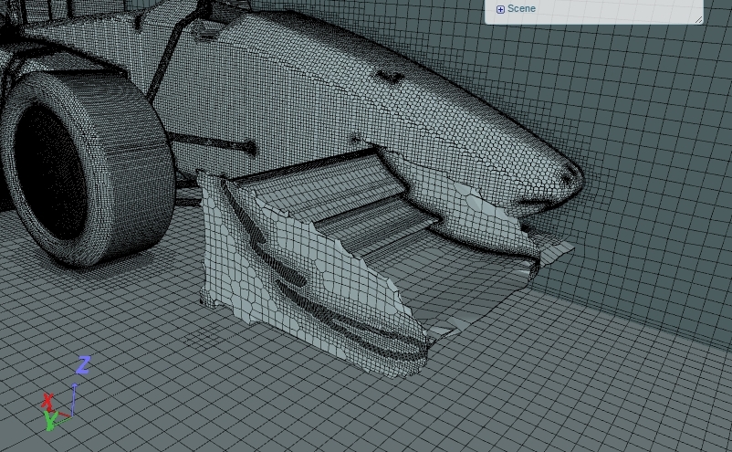
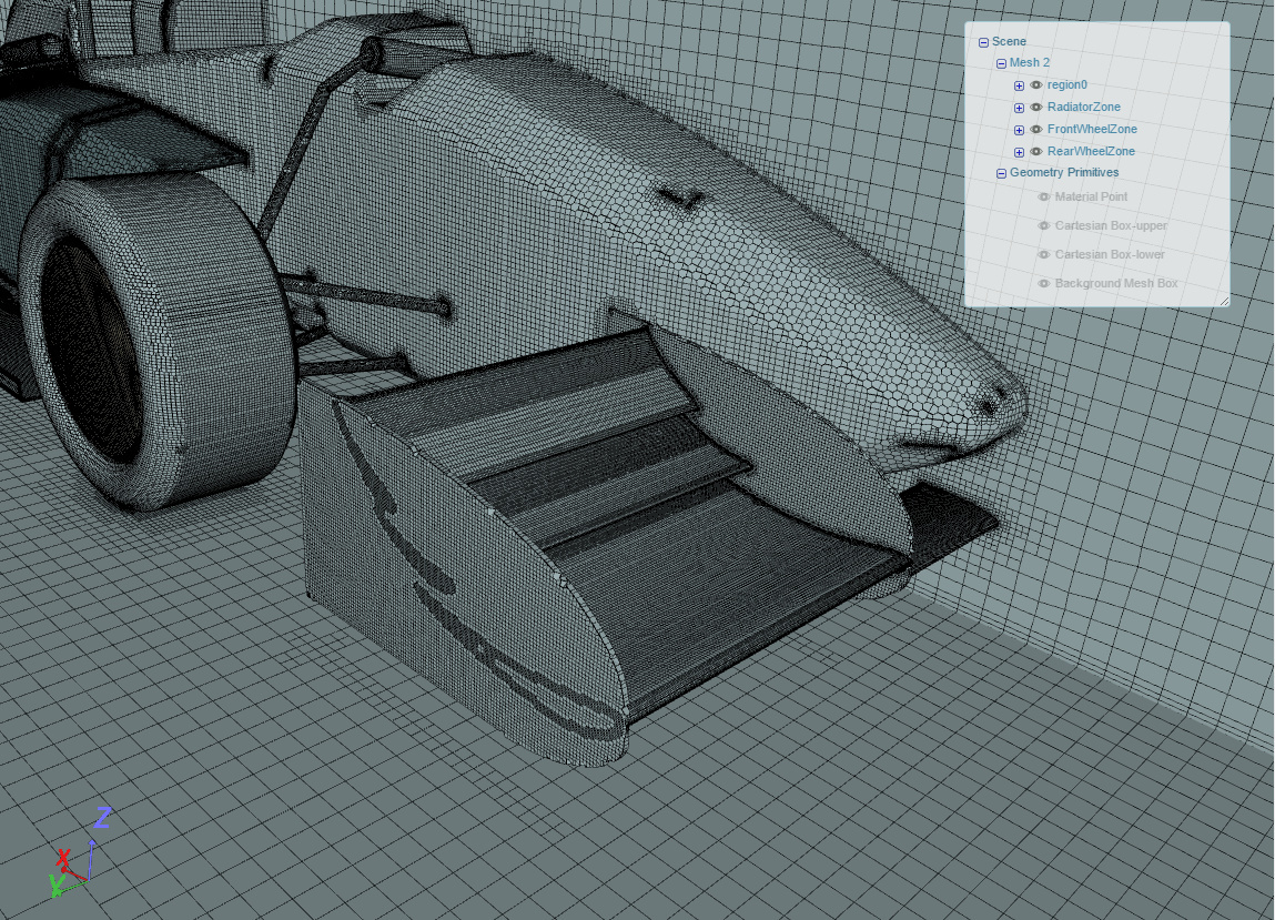
just try running the simulation and see what it does. I took a look at your project and the mesh looks not optimal for the front wing. See if it works for you that way if not I will jump in again.
Cheers,
Jousef
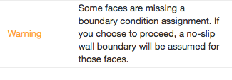
@jousefm, I just did start the simulation but I encountered this problem.
I checked the boundary settings and coincide with the settings of the second homework.
Gianni
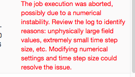
[UPDATE] the simulation run is interrupted after about 10 minutes with this message:
@jousefm I believe I am having the same or similar problem as @Gianni_S , I have also used SolidWorks 2016. I am not sure where the problem is coming from but, I believe it may be in the quality of the surface/mesh of the front wing.
This is my project link if you could please have a look https://www.simscale.com/workbench?publiclink=ac73b578-ce81-445b-86ed-c407481bd2ac
Cheers,
Jamie
I have A similar problem also used Solidworks 2016.
I did not receive the missing boundary message.
The mesh looks alright so far i know.
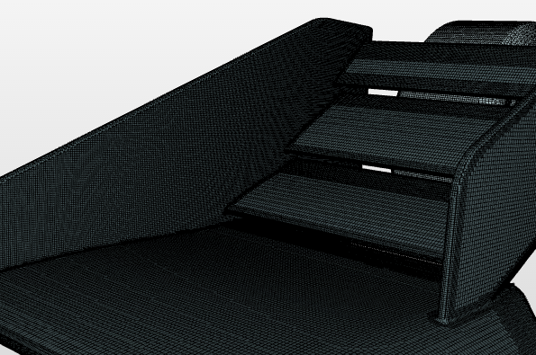
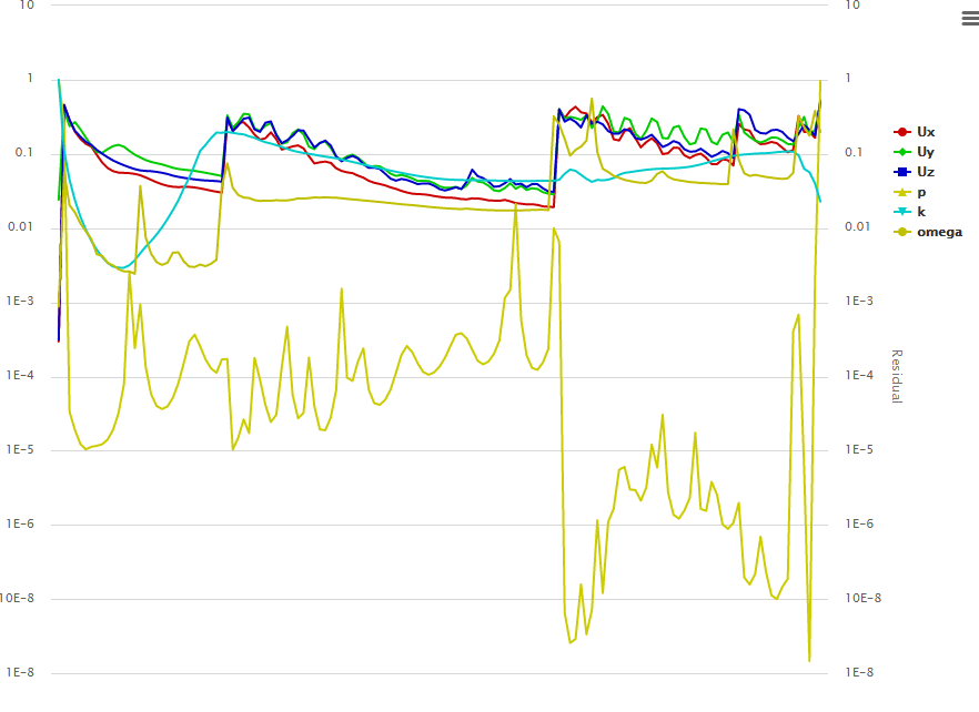
Also the simulation run plot looks very unstable.
Hello,
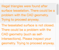
i get an error when meshing my model, but I cant’t find the problem. Maybe someone can have a look on it.
Best,
Philipp
Hi @PhilippB94,
meshing worked fine for your model: Your model
Proceed with the simulation.
Best,
Jousef
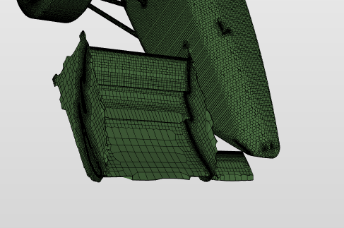
your front wing looks really coarse. I also tried a variation of some mesh parameters but it is still very edged.
@pfernandez , @anon96223049 do you have an idea what might be wrong? The standard settings from the instructions do not work in this case.
Best,
Jousef
Hi @Kolvenburger,
I was actually facing the same problem when trying to open the STL with CATIA V5.
You can solve it by deleting all the lines in the STL that contain the colour information.
Good luck!
Greetings,
Neither the script or the manual way is working for me when trying to merge the .stl files. What should I do to progress further? Thanks in advance.
which of the files has been updated again? the scale and position of the wingless model and the template front wing dont match.
Greetings @frankpot
Thank you very much for your help, I see that you managed to import your stl file as a part file in order to assembly it with you wing, how did you made it?, also every time I open my stl file in solidworks it takes a lot of hours to open, one time even freezed my computer, is that normal?.
Best regards.
Did you save the STL as ACSII? If you saved it as binary it will give problems.
@juansan995 Yea i did. I did nothing special. Just opened the STL and saved it. It took me around 30 seconds to open the STL. I have uploaded the S4 home work STL as SW file so you don’t need to open the STL. S4_home_work_model saved as SW 2016 file
I hope that it helps you!
I did. Still, the script fails after a few seconds and when I oped the files with Notepad, the text is gibberish. I’m lost. @frankpot
@jousefm, @Gianni_S, @anon96223049
I fixed the issue by renaming the front wing elements. To anyone having a similar issue with the mesh: just avoid using ‘-’ in the names of faces, e.g., rename FW_-_EPin-1 to FW_EPin_1.
1 Like
I redid everything (not using the script since it didn’t work this time either) and at least now the two parts get through in the same space successfully. In terms of fixing the orientation, should I reopen the part file of the wing and readjust the dimentions in reference to the origin, or is it a different thing?
Both STL files have a scale difference of 1000. While the first car has been exported with meter values, the wing has been exported in mm. I haven’t figured out how to scale imported geometries on CATIA V5 yet. Anyone have a workaround?