Hi,
i work with PTC Creo Parametric 3.0 and i wanted to ask how can i import the STL file?
I tried to convert it with FreeCAD but it doesn’t work.
Thanks in advance
2 Likes
@happy_gerrard …I am also having the same problem…my frontwing intersects with the diffuser. I use Solidworks 2013 . I think this problem is common to all solidworks user  …don’t know how to solve it
Having issues uploading project. Had it going for 12 hours today and still nothing!
i had the same problems. To solve this i created a new Coordinate System. To do this go to, Insert → Reference Geometry → Coordinate system.
As reference point I did the origin of the S4_home_work_model
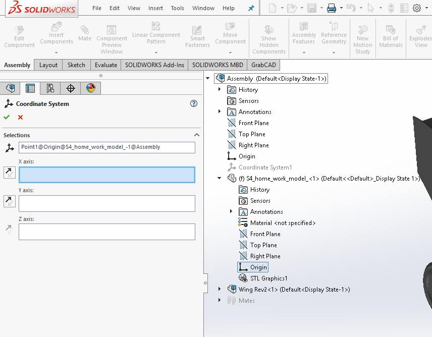
Now go to save as and select .STL. Go to Options and select Do not translate STL output data to positive space. Also you need to select a Output coordinate system(see picture below)

it took me 3 days to get a good stl file but this method worked for me.
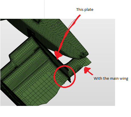
My first try had the same bad mesh. The problem by my was the "inside plate". The plate intersected the main wing. A simple Cavity solved the problem. A quick paint job:
2 Likes
i’ll try. thanks
Hey!
I’m getting the job aborted possibly due to a numerical instability error on my simulation, double checked the values from HW 2 and they look ok. Can this error be related to the CAD file (invalid intersection or something)?
Link: https://www.simscale.com/workbench?publiclink=48b91b25-857e-4931-b445-0b7fe2bd4833
Thanks, changing the coordinate system worked for me.
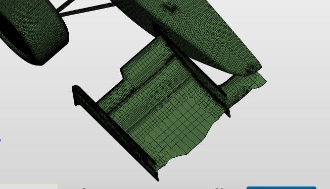
I successfully got the STL file working and uploaded it, but while meshing it gave me an error saying that my geometry might be open or interfering. I was unable to find the imperfection, so here is my project link, can anyone help me finding it:
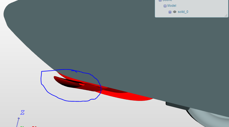
i think the problem lays with by the center of the wing.(see picture)
you probably used a open surface in your CAD program
I use NX10 and I have a problem with the script and with text editor merge. Windows don’t let me run with Powershell. I run it and appears an error message. When I try with the alternative method everything in the STL document is write with strange letters like in this image below, and I can’t merge them:
What can I do?
Hey! im using solidworks as well. CAn you tell me how you brought your geomtery of wing poitioned properly ?
is a floating wing alright ? do they need to be conected or intersecting? my wing is correctly positioned but i havent drawn any mounts to connect to the nose. should i proceed with the meshing with a floating wing ?
yes, no problem with a floating wing, i guess
okay. Thanks.
were you able to split the wing elements in solidworks?
Probably you saved your STL file as a Binary. You need to save it as a ACSII.
@jeettrivedi
I just did it with my own wing so it is possible. But I think it depends also on your own design.
import the foil twice if you want two elements, just be careful to displace the first one before importing the second.
Hello guys,
i have problems with importing the .stl model of the car to our CAD system. Our CAD system is CATIA V5. Every time i want to import the car model via insert --> existing component CATIA crashes. I also tried importing it to onshape, but it didn´t worked either.
Does anyone have the same problem or a solution for this problem?
Thanks for your help!
Hi all,
I’d love to hear from people who have used SolidWorks for this exercise.
What is the workflow to get the model into SolidWorks before you generate the front wing geometry?
I can import as a STL Graphics body - which seems almost useless (cannot offset surfaces, measure from existing FSAE car geometry and so on)
If I try to import as a solid or surface body I get an error message (too many facets)
I’m using SWX2015
Is it possible to get the geometry in STEP format?
Thanks,
Nick (Australia)