Recording

Homework submission
Submitting all three homework assignments will qualify you for a free Professional Training (value of 500€), a certificate of participation and will give you a chance to win a special price!
Homework 3- Deadline 17.04 12:00pm
Please use the form to submit your homework
Exercise
With this homework we want to put you into the seat of a F1 race car designer.
Your task is to perform a flow simulation of your own rear wing design which you can create with the
parametric model we provide. For this you have to do the following steps:
- Modify and export the parametric rear wing model with CAESES Free. The exact instructions for this can be found below
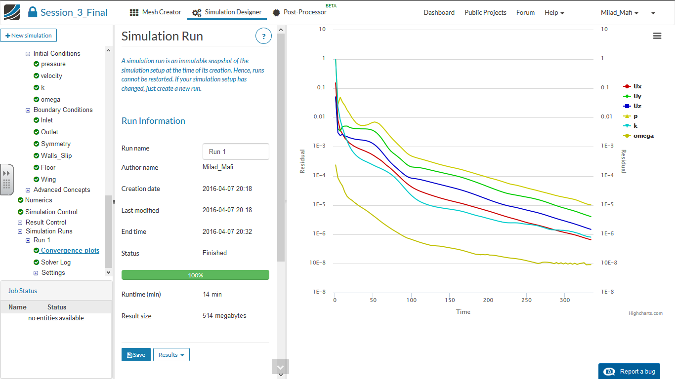
- Setup a external aerodynamics analysis of the wing for 40m/s, 60m/s and 80m/s. Please use the same simulation setup from the previous homework assignement
Step-by-Step instruction:
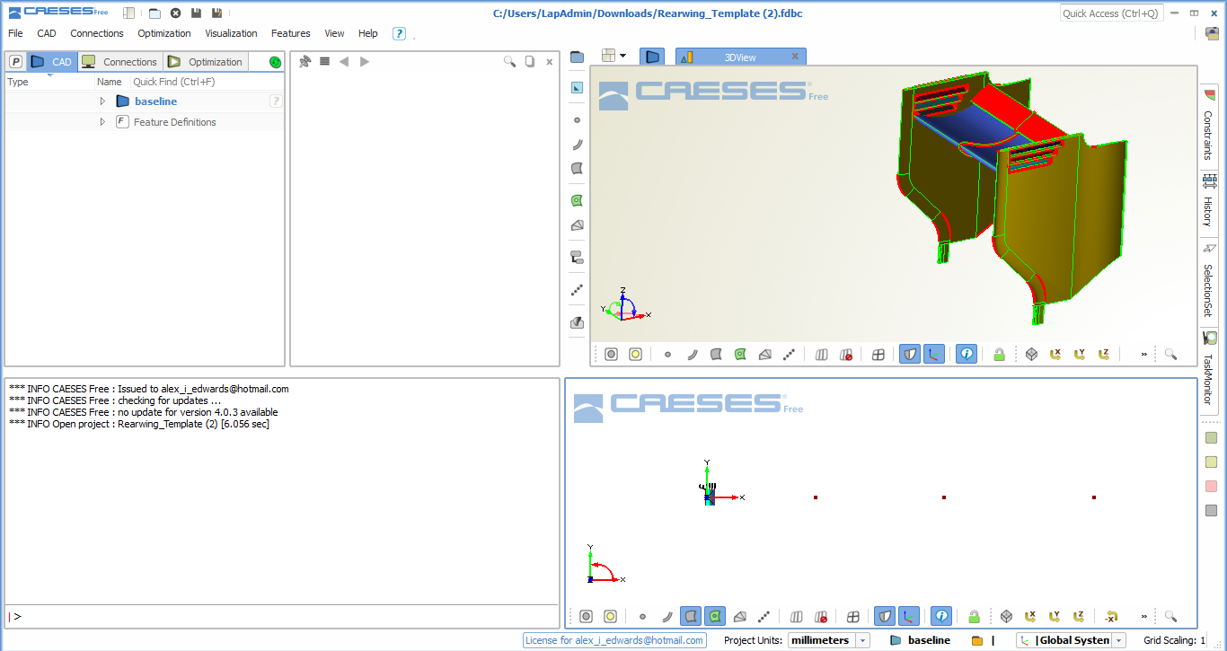
In the following step by step tutorial you will understand the basic operations to manipulate the graphical user interface to modify the given geometry.
Note: The colors of the rearwing surfaces can may be different
The 3D view window it’s window that we can use to visualise and manipulate our geometry, the lower bare contain functions that facilitate the manipulation operations.

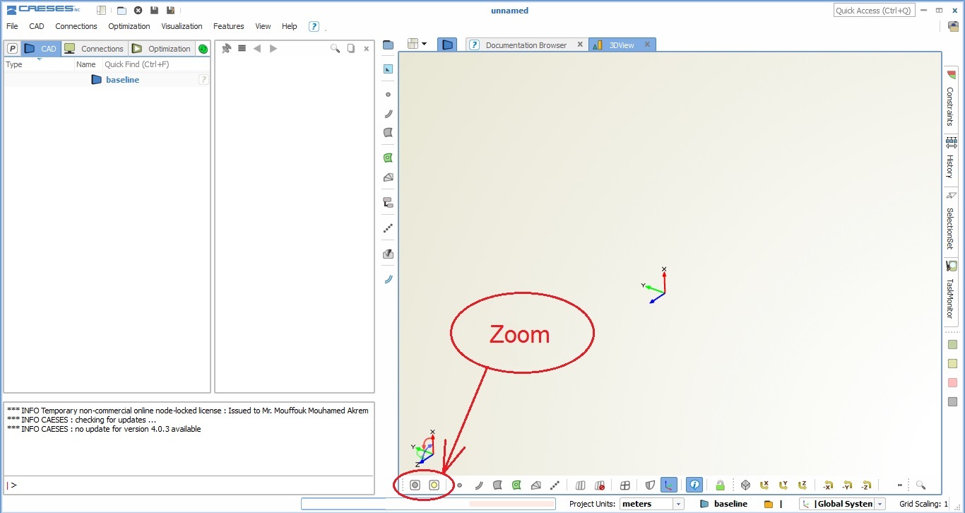
Zoom operations can be used to fit the view of your model in the center of the graphical window, you can click directly on this operation or you can reach it by the keyboard key F10.
The filters allow you to show or hide a specific entity like points, lines, surfaces or Breps by clicking on the specific type you will hide the selected entities.

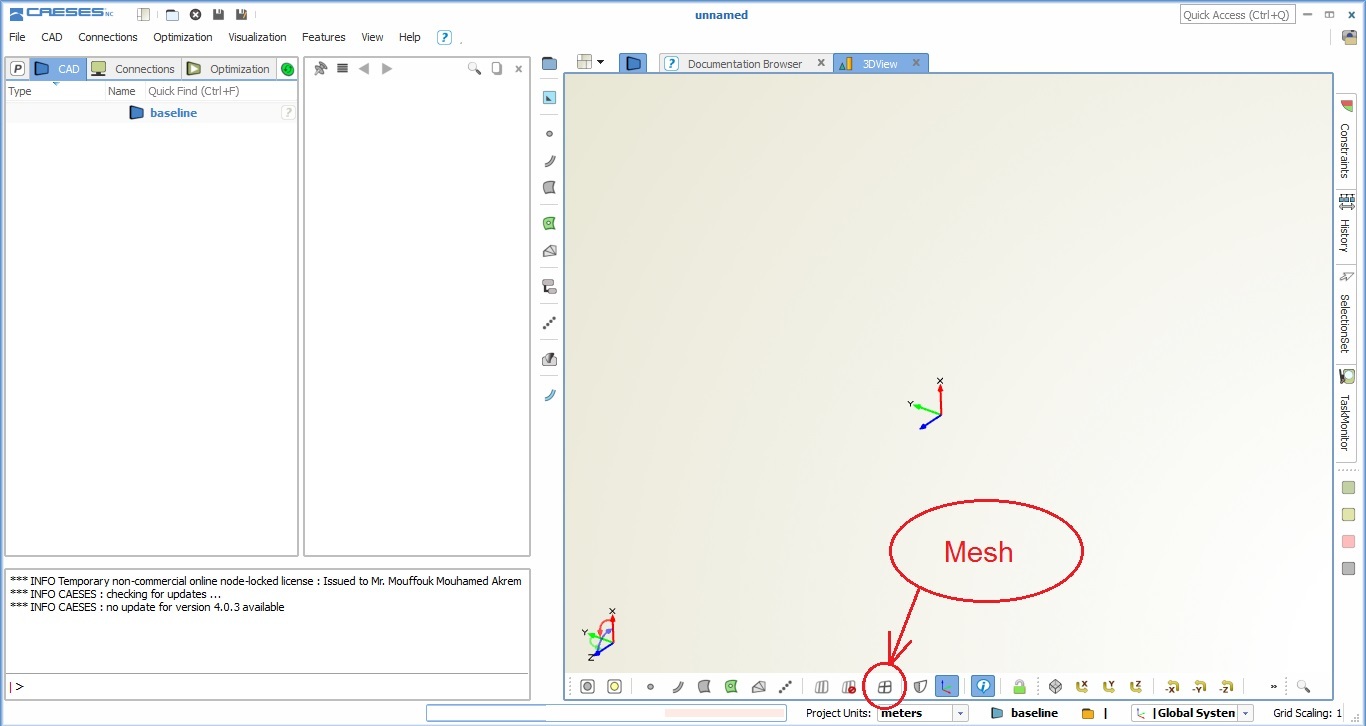
This function allows you to show the mesh of the geometry.
This function is to create a symmetry image for the geometry, like in our model we have half model and we can use this operation to create a symmetric image to see the full model.

This operation gives you the possibility to create a view projection along a specific axe like is shown in the icons.

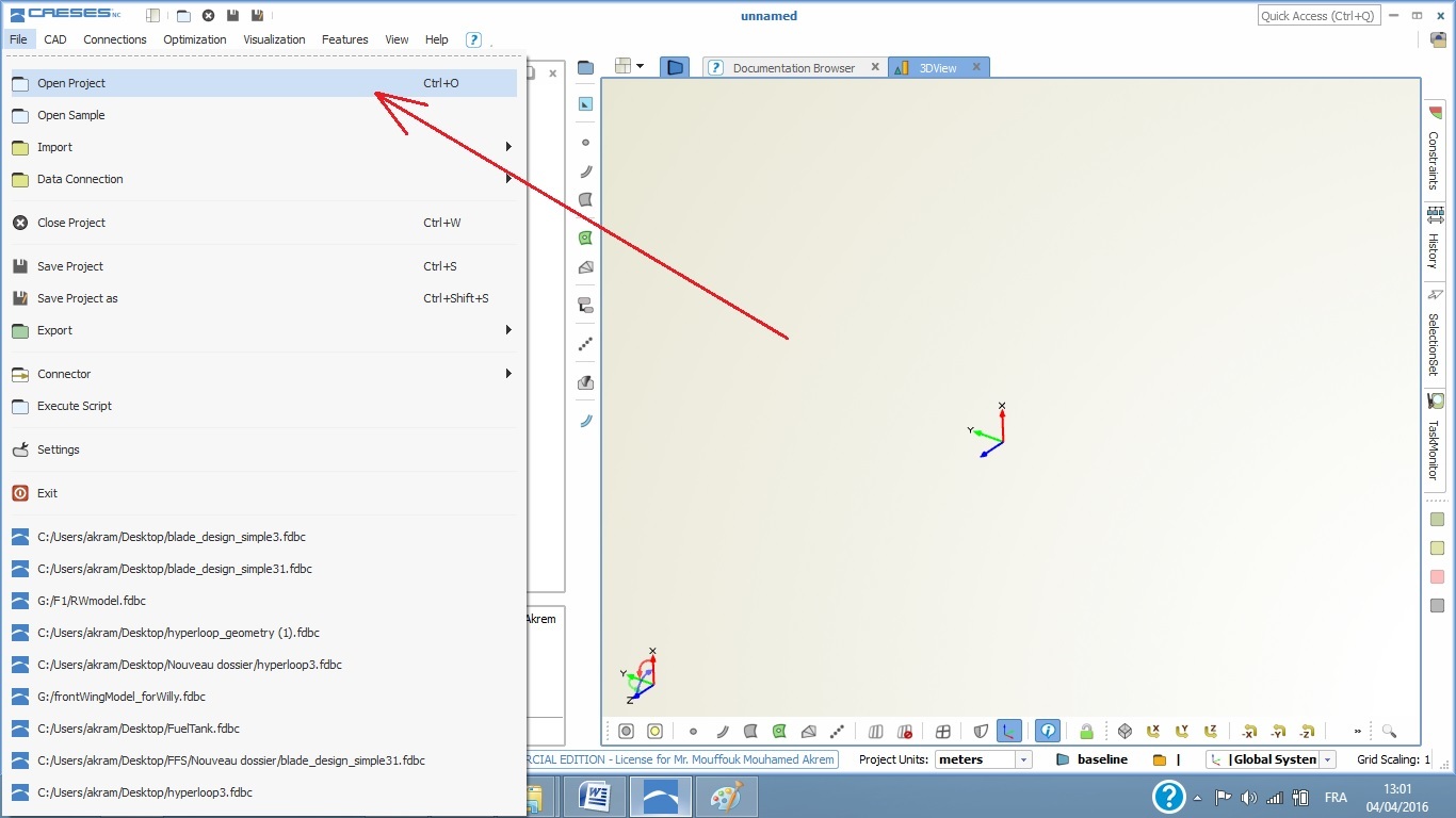
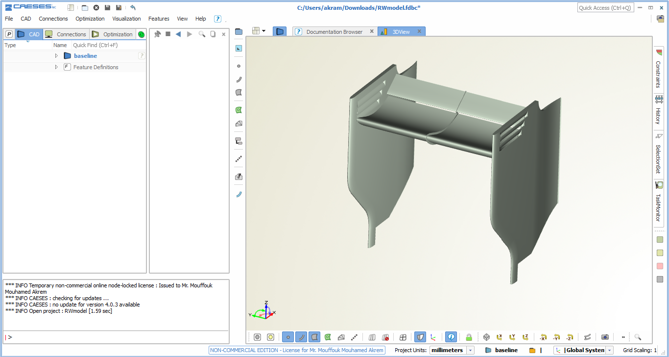
To open an existing mode using CAESES click on file > open project then search for the file of your model in the specified path where you have save it or directly using Ctrl+O commend.
When the model is opened you can see it in the 3D view window if it does not appear in the 3D view window, you should just click on zoom extended or press F10 and the mode will be centered in the center of the window hide also points and surfaces and click on symmetry image to get full 3D model.
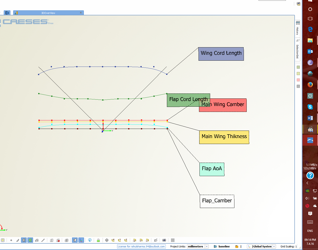
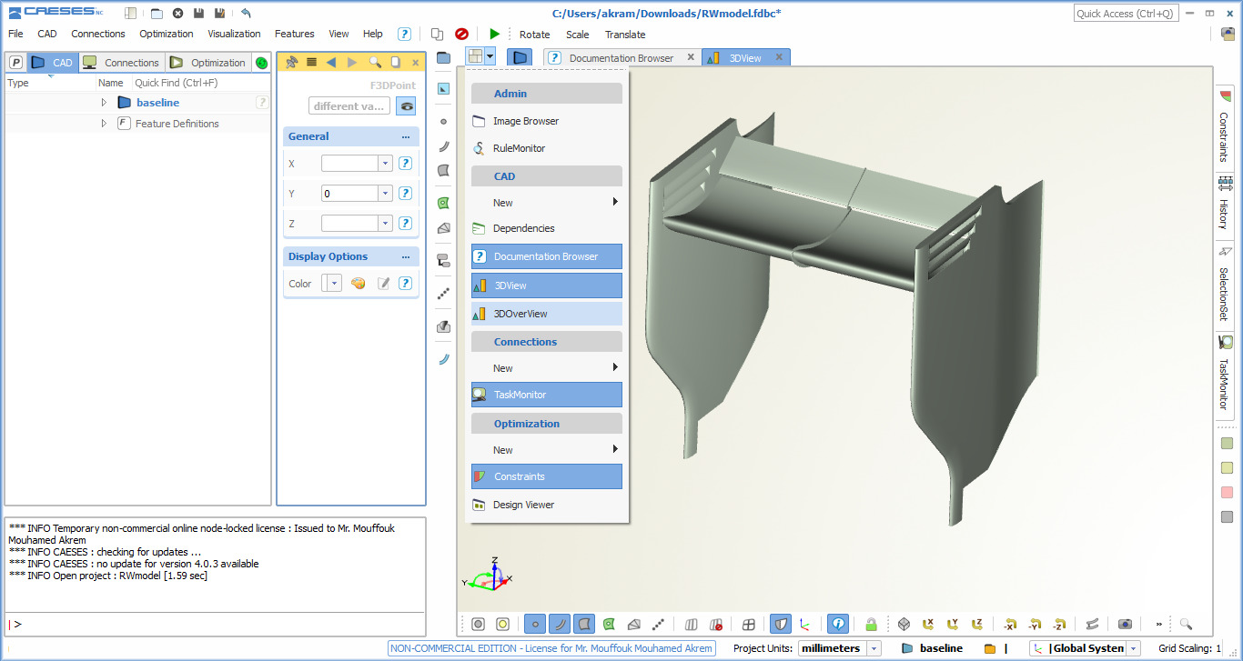
This model is parametric model designed using metasurface technique and the distribution of these parameters in the wing span wise is controlled by functions that we have to visualize it to do this right click on overview then select 3D over view, a new window will appear in the lower part of your screen.
On the new window click on surface, BREP and mesh filters to show only the lines and the points then click on +z projection view to have plan view, you can turn your view to the right axes using the arrows key with the key board.
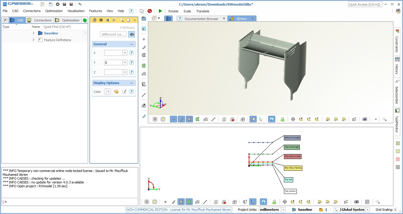
Now you have the functions and the 3d model view you can manipulate the functions and see how the functions influence the model.
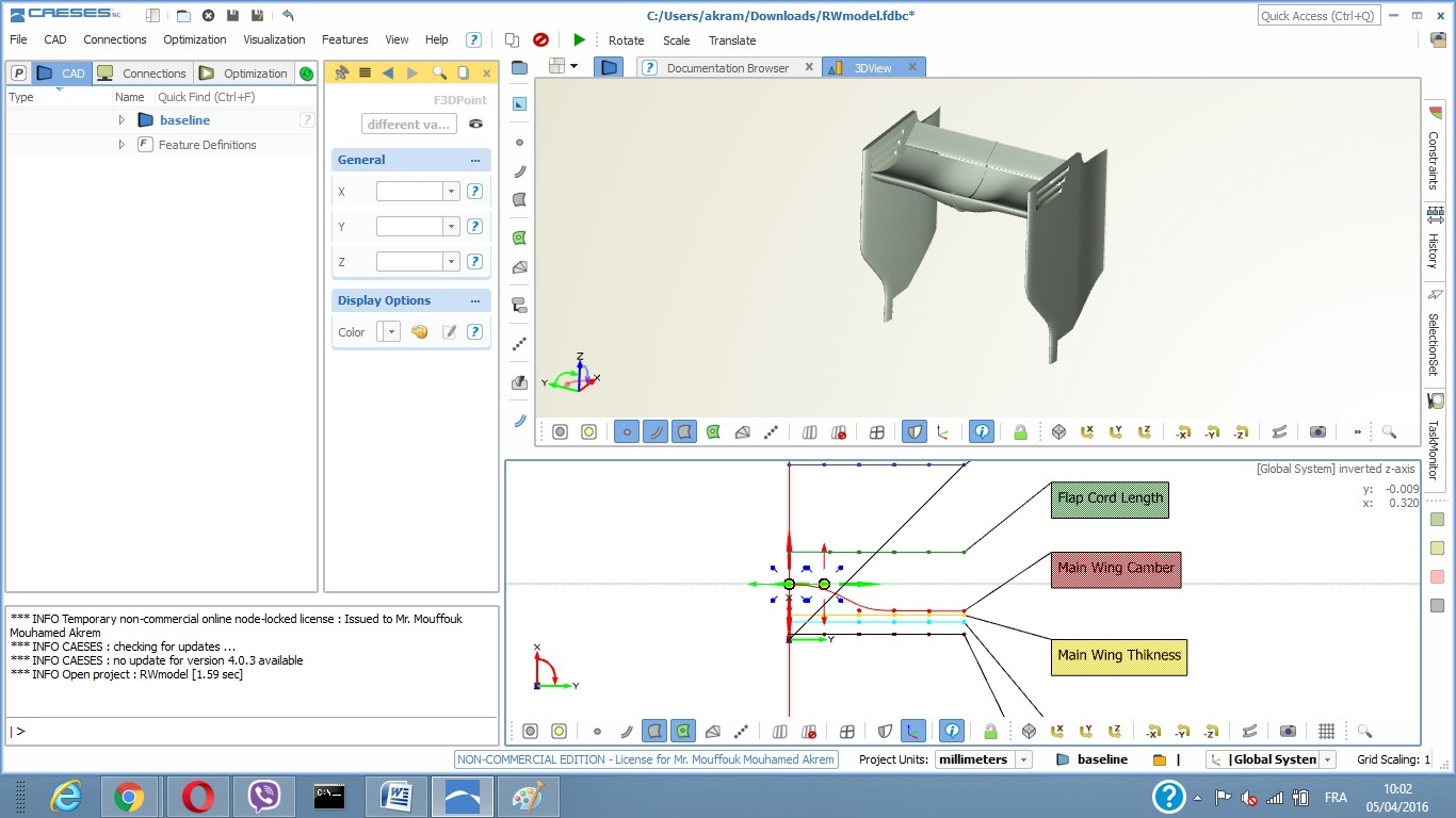
To do this you have to decide which parameter you want to change, go to the specific function and select one or more points from the function that you want to change, keep holding the selected control points and move your mouse in the X or Y direction and you will see you model moving at the same time.

Once you finally modify your model as you want now it’s the stage to save the model and to export it to run it later in SimScale.

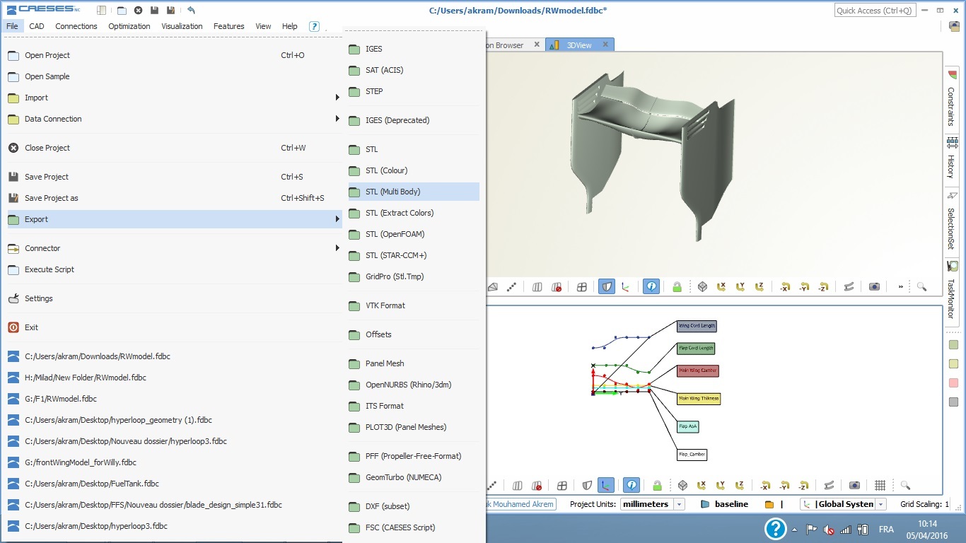
To save your model click on File > Save specify the path where you want save you file. To export your model click on File > Export then you will have a large library of formats that allows you to export surfaces and meshes for our work we will use STL (Multi Body) to use a model with separated boundaries.
Upload to SimScale
Please create a new public project.

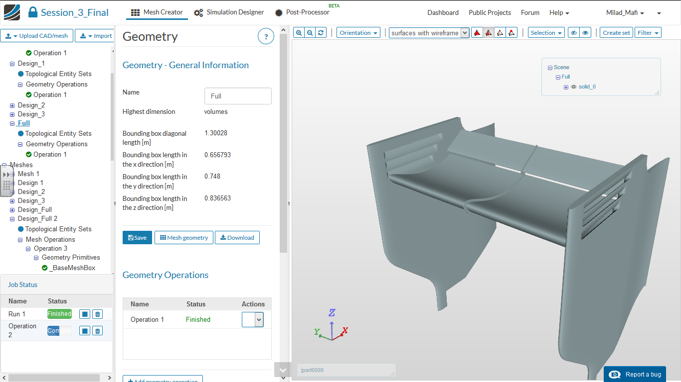
Then open the project and switch to the Mesh Creator
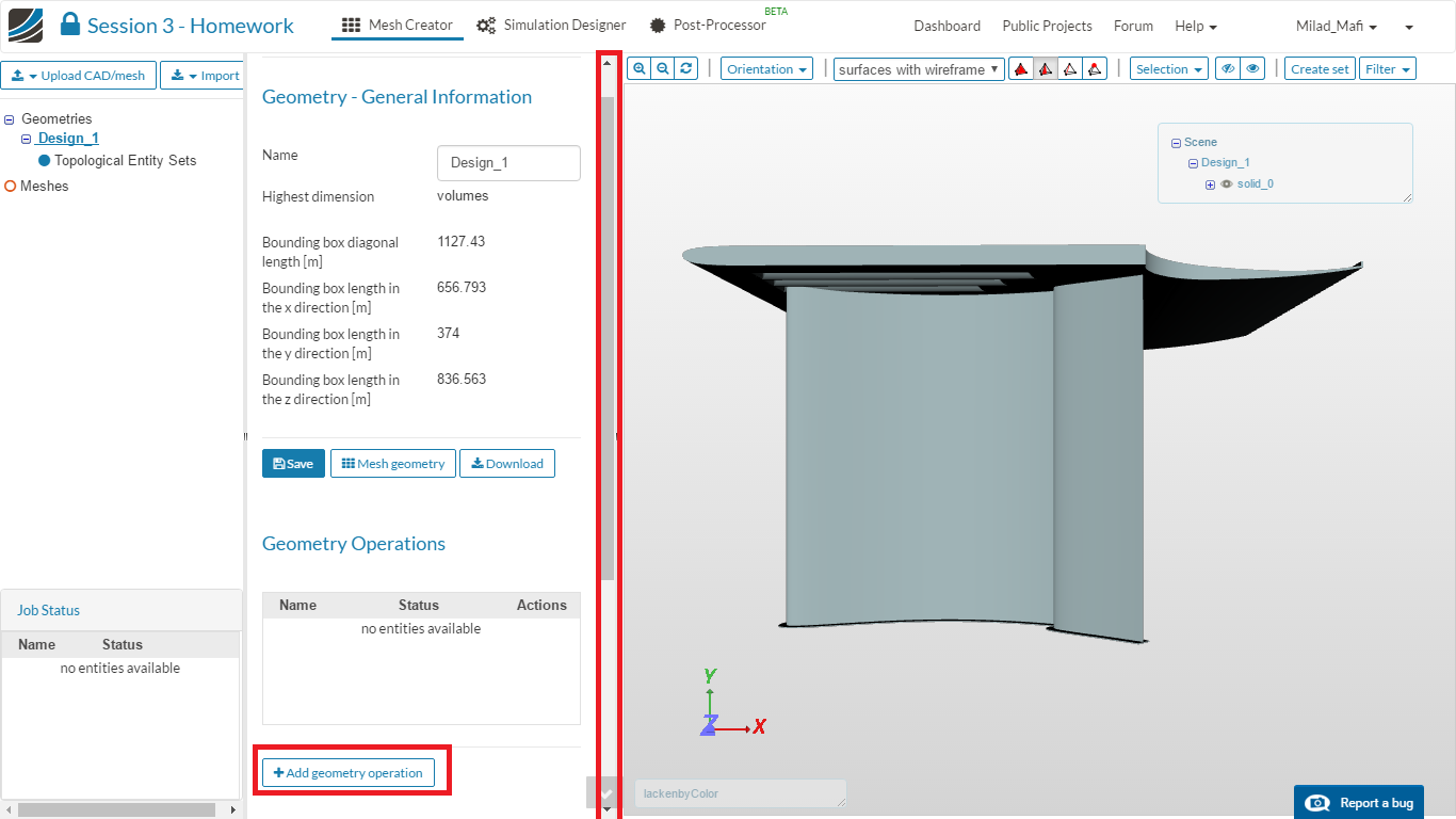
There you will find some information about the dimensions of your CAD model. Since the (the orginal model was created in milimeter we will perform a scaling operation. Please click on the Add geometry operation button.
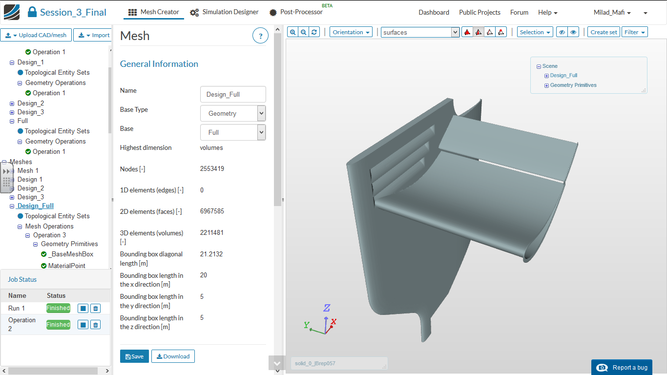
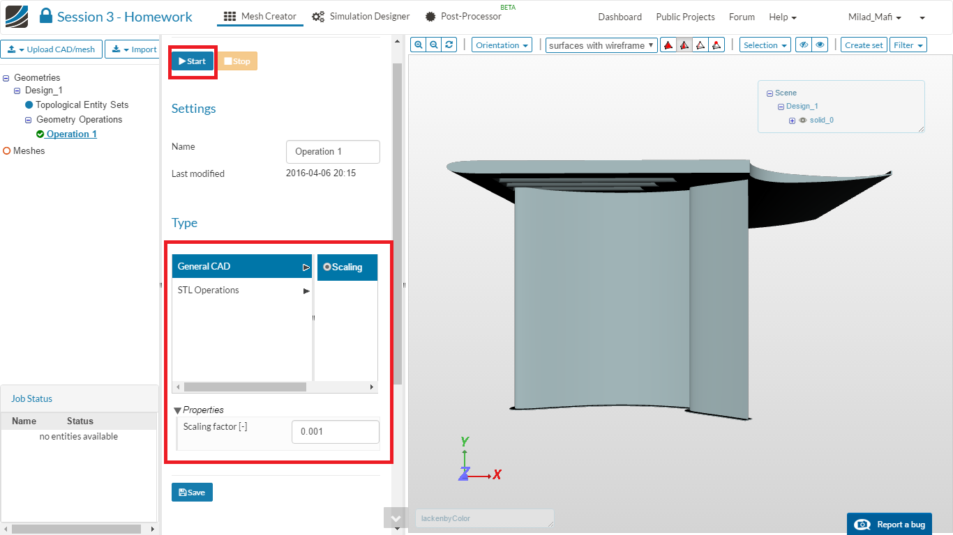
Choose Scaling as the operation and define a Scaling factor of 0.001. Please change your changes and start the operation.
Now you can continue with the instructions of the last homework assignement.