@Milad, thanks for posting this. But I’ve got a quick questions.
There is mentioned of “Overall you have to create two meshes as well as six simulation runs.”.
I’ve quickly gone through the tutorial, there are 5 velocities Under the ‘Step-by-Step’ instruction, and there is (1) set of instruction for meshing. Is there another variation of meshing we just pick any (3) velocities for our homework?
1 Like
Inspecting the mesh generated with the given parameters, I found it was not fine enough.For example you can look at the gap separators and other small details, such as fillets and faces.
The solution was to augment the refinement levels in the Surface Refinement operation, from 7-8 to 8-9.
Waiting for the posprocessing instructions.
Hi,
sorry for the confusion. In detail you have to create:
- One mesh for the rear wing with louvres
- One mesh for the rear wing without louvres
- Simulation at 40 m/s, 60 m/s, 80 m/s for the reat wind with louvres
- Simulation at 40 m/s, 60 m/s, 80 m/s for the reat wind without louvres
Overall you need 2 meshes and six simulation runs!
Cheers,
Milad
1 Like
Hi,
you are right. It would make sense to use a finer mesh. Would you be so kind and share your investiagtion about the difference between your mesh and the initial one?
Cheers,
Milad
Shure, look at this pictures:
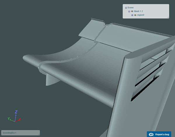
Mesh with tutorial parameters (Surface Refinement levels 7-8)
Mesh with finer refinement (Surface Refinement levels 8-9)
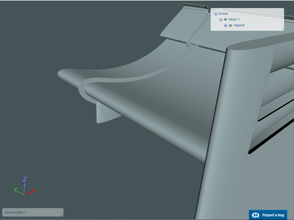
You can see the ficticous serrated edges on the gap separator and low quality surface of some end plate fillets for the first picture. Those are absent from the second picture.
3 Likes
Hello all,
I hope you all are enjoying this webinar as I am.
It might be a silly question and sorry about that but I would like to know some details of the material point.
- Is the material point the center of mass of the half of the rear wing?
- If it is, I can get it by any CAD software but can you get it by Simscale platform?
Regards,
Andres
@agarciadelgado - The material point is used to detemine which part of the mesh will be kept (depending on whether you are doing an internal flow simulation or an external flow simulation.) Take a look here for a detailed explanation with images - Main Settings for Hex-dominant Parametric | SimScale
Best,
Anna
2 Likes

Hi, I have a question about surface refinement level that we have to use for this homework, i have done a first simulation with refinement levels 7-8 following the tutorial and the results achieved convergence in about 20 minutes (32cores) with mesh created in about 11 minutes. After i have setted the same simulation with finer mesh (refinement levels 8-9), and the time for create mesh and to achieve convergence increased respectively to 33 minutes and 77 minutes! I had a look at the results in terms of force plots and seems similar in their final values, another thing is that, with refinement parameters setted like in the tutorial, the simulation time in the first run stops at about 550 seconds whereas in the second run, with finer mesh, it stops at the setted end (1000seconds).
How can I evaluate in post processing if the benefits of finer mesh balance the increase of execution time and if is it necessary to use finer mesh?
Thanks, Best regards
Here the link to my project
1 Like
Well, without geting too deep in the theory, I can tell you that:
-
Increasing the refinement level is equivalent to specify smaller cells, so the total number of elements increases, if I am not wrong in this particular case it doubles from 2+ million to 4+ million. That explains the increase in computation time (and memory usage, tough I think you didn’t notice that).
-
I think the convergence is expected to be faster for the model with the less number of cells. That is because the bigger cells capture less variations in the flow. You can think of this as some kind of ponderation over the flow variables. But you risk losing accuracy.
-
If the simulation reaches the 1000 steps (be careful with this, it is not seconds), this means it hasn’t converged. This is, at least to the control level indicated in the numerics section (default residual of 1e-5). If it reaches this level for all variables before the maximum number of steps, the simulation stops (in your case at step 550). Anyway, this doesn’t assure that the result is correct.
-
To asses the benefits of a finer mesh, the usual procedure is to simulate with many meshes (a minimum of 3), and compare the results of interest variables. Specially see if they converge to some value. You got it the right way by comparing the forces, but you can share with us the variation and we can discuss. If it is small enough (say for example less than 2%), I guess the higher computational cost is not worth it. I think it could be in this case, as the pressure field is what dominates this forces. But be aware that this is not general, as for example if the interest variable were the velocioties or formation of vortexes, I think it won’t be so close.
-
Also be aware that I raised the question of the refinement levels because the geometry was not being correctly modelled. In my opinion, this is not acceptable.
Greetings, hope I could shed some light on your doubts.
4 Likes
if i try to go to my dashboard I receive the following message:
This XML file does not appear to have any style information associated with it. The document tree is shown below.
NoSuchBucket
The specified bucket does not exist
https://www.simscale.com
B40F9CD44E9B7D82
FAgzYEaKRI7n31dm8JTqJcfvc98fSj+JYQvu8Zex1Gd0kOyiGnWapQxmAjN3MlZToZhEej+S2ho=
What can I do?
@aceci - it’s a technical problem from our end, we will get the platform up and running as soon as we can!
I’ve followed the steps to mesh the geometry as described and although the log states there are no errors it has failed the mesh quality check.
Does it make sense to run the simulation with the poor mesh? Seems a strange outcome for a tutorial
Hi,
this the my mesh log file:
Checking final mesh …
Checking faces in error :
non-orthogonality > 70 degrees : 0
faces with face pyramid volume < 1e-13 : 0
faces with concavity > 80 degrees : 0
faces with skewness > 4 (internal) or 20 (boundary) : 0
faces with interpolation weights (0…1) < 0.02 : 0
faces with volume ratio of neighbour cells < 0.01 : 0
faces with face twist < 0.01 : 0
faces on cells with determinant < 0.001 : 0
Finished meshing without any errors
Finished meshing in = 214.58 s.
End
Finalising parallel run
There are no errors regarding the mesh quality. If you are talking about this one:
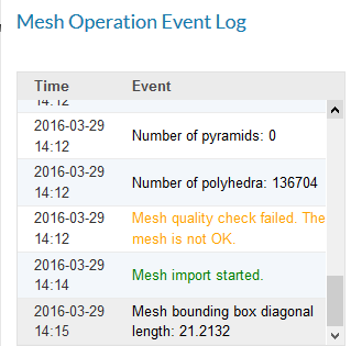
Don’t worry. This is a different kind mesh quality test which is not mandatory for CFD simulations.
Cheers,
Milad
2 Likes
Yes that is the one i see, thanks
Thanks for the answers man  , yes of course i know about the increasing of computational time and memory usage due to number of elements increase. About the values of forces i see that there is roughly a difference in a range of 2% to 6% in the results final value (considering only the pressure forces and moment) between the two simulations.
Hi
I got for the F1 aerodynamics Workshop Homework 2 a Mesh Error for the Rear Wing geometry (the one with loures). The Rear Wing _2 geometry (withouth loures) meshed without problems
These are the Error messages in my Mesh Operation Event Log:
The tesselated surface is not closed. There could be a problem with the CAD geometry (such as self-intersections). Please inspect your geometry. Trying to proceed anyway.
Illegal triangles were found after surface tesselation. There could be a problem with the CAD geometry. Trying to proceed anyway.
Mesh quality check failed. The mesh is not OK.
This is the project’s link
Please advice
Thanks for your help
Regards
Jorge