@jousefm Aaa… now it’s clear. BTW: this is happening when you skim through something or don’t read at all I just ran through the text, noticed “3 NOT 3*t” and wrote my reply
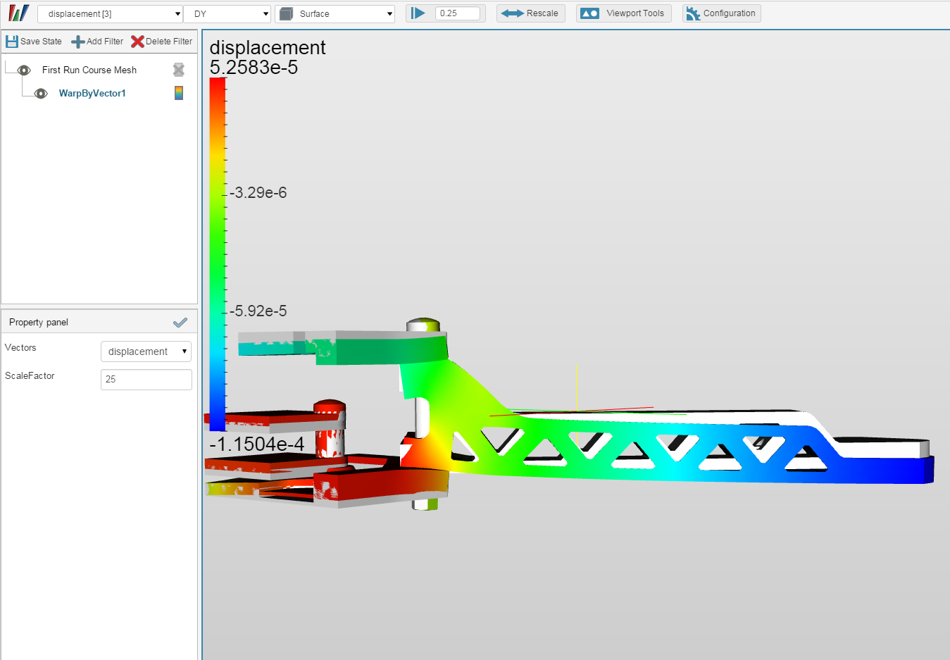
In terms of the plot: why do you both have two negative displacements here? As far as I can see – this time I try to be careful – there is no Gravity, so for no force state we should have no displacement at all (this fits; Milad’s e-22 is in fact zero too). But later we should get some positive displacement in constant direction. I mean the sign in front of it (plus or minus) should be constant, shouldn’t it?
In our case the lift force pulls drone’s frame up (however is sounds, in Yplus direction) and you and Milad have negative displacement values. Moreover, in Milad’s case the scale is odd too. – Pretension on screws? Because this is the part I don’t get: the way we model stress generated by tightened screw.
What is this External point: Explicit definition? In mesh tab I switched to snappyHexMesh and displayed it as a point. It’s located more or less on screw axis, somewhere in the middle of its length. Now, why do we define it? What for? And where is the preload from the first picture if we set Translation and Rotation in Remote displacement at zero. Physical Contacts between the screw and drone’s frame don’t do the trick?
Hi @anon5767293,
maybe I can shed some light on this.
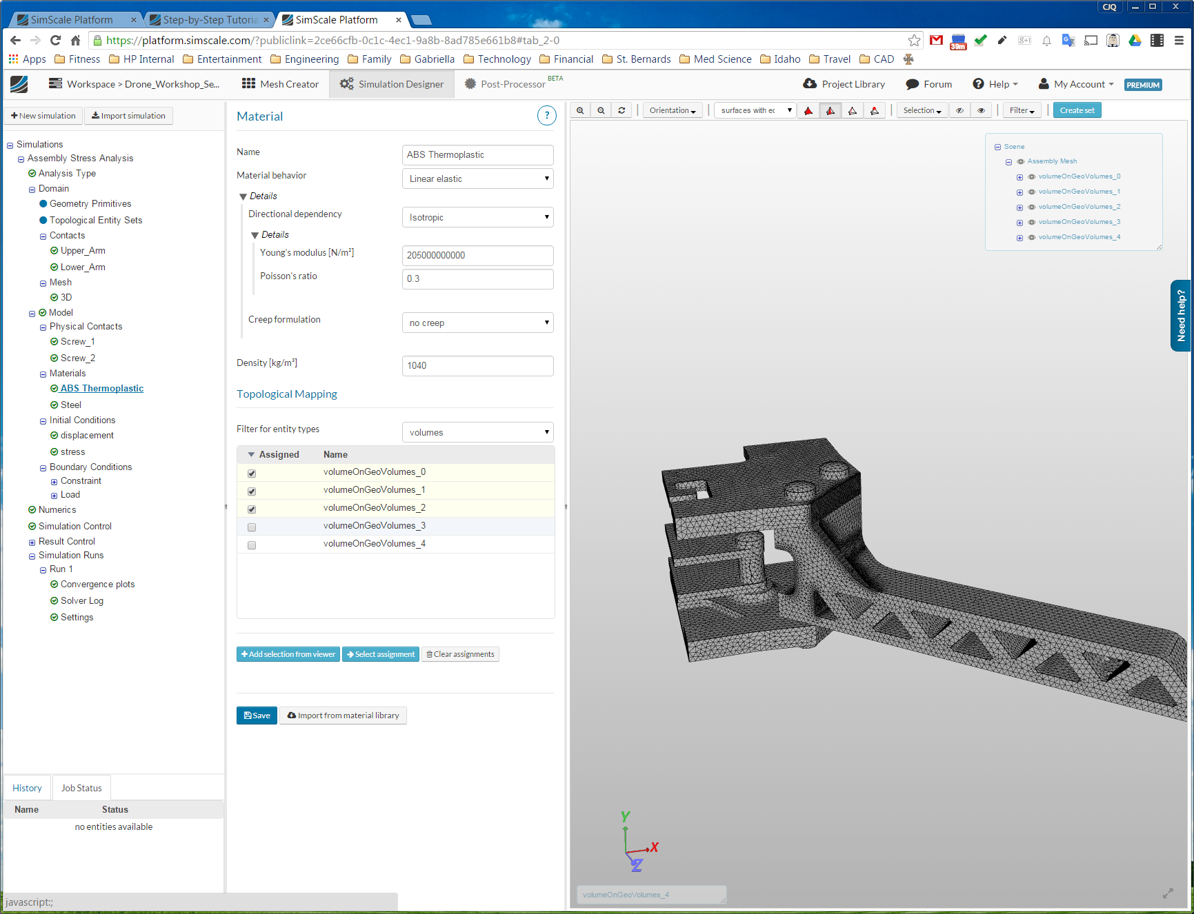
How we define the pre-stress in the bolt similar to what is done in an interference fit: we intentionally design the geometry of the bolt a little shorter and the repositioning of the contacting nodes on the surface of the contacted body will result in a strain and thus a stress in the bolts. In real life interference fits are created with expansion/shrinkage during heat treatment (and normally not on bolted connections), but for our purposes this should work fine with the shortening of the bolt.
The question is now, why do we define this mysterious remote displacement?
The short answer: to make our life easier.
The longer one: If we use a frictionless physical contact, the bolts movements are not statically defined, they are free to rotate around their middle axes and also free to slide in X- and Z-direction (imagine the contact zones being made of ice). To prevent this we use remote displacements, put each somewhere at the center axes of a bolt and restrict rotation around the Y-axis and the two rotations. So we create a new node, restrict its rotation and displacement accordingly and connect via RBE3 connections to the bolts.
Now this should in theory should be enough to get a statically defined system, but still the z-movement may cause problems. The bolts are only restricted from moving along the z-axis by the two opposite contact zones, so finally the contact forces. If those two opposite forces are not exactly equal (which is very likely in a numerical simulation), we get a resulting force which will accelerate the bolts along z. In a static analysis this will lead to an unsolvable system or totally unphysical results (almost infinite displacement). So we use a trick: We pose the remote displacements at the two opposing ends of each bolt and restrict the z-displacement. BUT since we selected a deformable behavior, the two ends are still able to deform in z-direction, only the total “average” of the displacements has to be zero. And we actually would expect this to happen.
I hope this is clearing up some of your question marks regarding the remote displacement boundary condition and why it is used here. You can also find some additional information about this boundary condition in our documentation.
We could actually check if our approximations are correct if we would set up a frictional contact (and possibly use a dynamic analysis for the z-Force problem) and compare the results with our approach. If you want to go this extra mile I would be happy to assist you if problems appear.
Concerning the total displacement at the end of the arm, I’ll have to take a closer look at the model to see what actually makes sense. Theoretically both positive and negative values could be correct because of the pre-load, only a positive trend has to be visible when applying a positive Y-force. I’ll check it and come back later with my conclusion.
Mea Culpa! I uploaded the wrong screenshot (of a different simulation setup which is not relevant for this homework). I just corrected this mistake. Your force plots are absolutely right!
When I have created the new and refined mesh it seemed that all BC’s and interfaces have lost their defined geometry definitions (connections to surface ID’s, volume ID’s etc.) Hence I had to re-enter all this information again.
As I see it, in this case only mesh settings is changed. Geometry ID’s (surface, volumes etc.) are still the same in the new mesh, so is there a way to avoid the tedious work of having to define/re-enter all ID’s to constraints and interfaces again ?
Unfortunately it is not possible to ‘map’ boundary conditions etc. to a new mesh. But a smart work-arround is to copy the initial simulation and to change the mesh (click therefore on the Domain item in the project tree**).
@anon5767293 when I look at time step 0.25, and the displacement in the y direction it does look like the bolt preload is causing the initial negative deflection.
@anon67859130@jousefm there are a couple areas I am still confused on and I hope someone can clarify things for me.
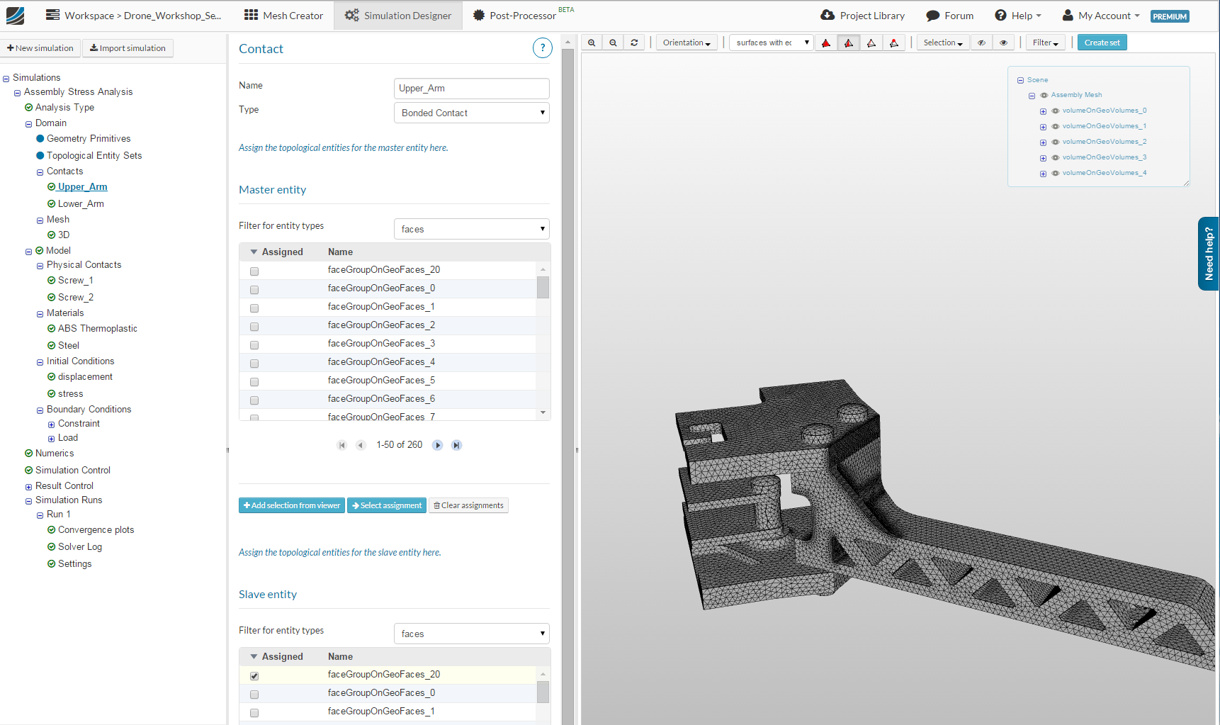
I am not sure what the difference is between the Contacts and the Physical Contacts. We created two contacts between the plates and the arm. Since this is a Bonded Contact, we basically glued these three parts together. One option was a sliding contact which seems like it would have been a better choice since we are trying to see the effects of the clamping force.
The way I understand it, the Remote displacement is just a way to stabilize the bolt so a solution can be found. In other programs I have done this by using springs to ground, but I think this accomplishes the same thing.
The main difference between a contact and a physical contact is that the first is basically just a linear constraint between nodes and the second one is highly nonlinear.
A contact is mainly used to connect/weld/glue different parts of an assembly together that actually behave like a single solid, but may consist of different materials. The bonded contact does not allow any relative movement between the selected faces, whereas the sliding contact allows relative movement in tangential direction (of course computed on the initial mesh and not updated during calculation), but the normal direction is fixed.
In a physical contact, the relative movement is totally free, only penetration is restricted. The relative distance and the surface normals are updated in every iteration and measured in the deformed configuration. The physical contact type allows also separation of the contact surfaces, which no simple contact type allows. Additionally it also allows to take into the account the friction between contacting surfaces.
You’ll also find some useful information about contacts and physical contacts in our documentation.
If we would have chosen a sliding contact in the example, we would leave the arm free to move in x- and y-direction, since only z-movement would be coupled to the frame. This would require an additional contact between the bolts and the arm to prevent the rigid body movement.
Another possible solution would be to use a physical contact with friction for the connection of the arm and the frame. This would restrict the x-z-movement, but the price would be a higher numerical complexity, runtime and memory requirements.
Concerning the stabilization of the solution with soft springs attached to the ground. This is a very good idea and common practice. We are already working on this feature and it will be a part of a more general possibility to define all different kinds of structural elements (beams, shells, dampers, cables,…).
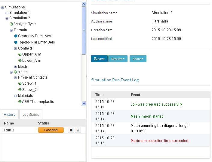
I tried to run the level 2 tutorial but it seems like I am running out of space on my account. I had to delete one of the tutorial from session 1 to be able to set up the fine mesh simulation. Is this normal, or does the quota on my account is abnormally too low?
Hi @anon20963368, if it says you ran out of space when you were trying to create the mesh or run the analysis you probably need to check to see if you set the number of computational cores correctly. The amount of memory you get and the amount of temporary storage goes up with the more cores you use. It should be set to 8 when you create the mesh. This has gotten me several times.
I don’t know if this is the issue you are having but it’s worth checking.
Is anyone here using paraview,if so is it faster than the browser simulation run??
Since once simulation takes about 76 min…
Eventhough my pc nor my net connection is slow.
Hi, my displacement plot looks ridiculous and unexpected… can’t find the error, thought it might either be in the load boundary condition but i don’t think it is. any chance someone could skim over and look for a mistake?
Hi @uzair_m, Paraview is only allows you to view your results locally from a Simscale simulation. It does not allow you to run the simulation locally. My simulations for this problem seem to be taking about 70 minutes as well. I don’t think Simscale is as fast as some of the other FEA packages I have used that run locally, but at least I do not need a $4000 PC to run FEA anymore.
Hi @1318980 (Darren), I looked at your model and I see a few things that might be causing your problem.
When I look at your defined contacts, Upper Arm and Lower Arm, I only see the Slave entity checked. I do not see a Mater entity checked. I know when I go back and check my model, sometimes the check boxes just seem to clear themselves. You may want to check the Physical Contacts as well. The boundary condition in the results seem to look reasonable, so this may just be a glitch in the display or just on my system.
I submitted my homeworks both times now and hope that i can get the seminar in the end. But i am already trying to do some other simulations.
Can i already delete the projects of the first homework to get some more free storage space?
 I just ran through the text, noticed “3 NOT 3*t” and wrote my reply
 – there is no Gravity, so for no force state we should have no displacement at all (this fits; Milad’s e-22 is in fact zero too). But later we should get some positive displacement in constant direction. I mean the sign in front of it (plus or minus) should be constant, shouldn’t it?
 direction) and you and Milad have negative displacement values. Moreover, in Milad’s case the scale is odd too. – Pretension on screws? Because this is the part I don’t get: the way we model stress generated by tightened screw.