In my case it took 76 minutes for mesh around 4.4 mln (downloaded results file about 850 MB).
I guess you missed with the Number of computing cores. If so, then please change it to 32.
Hi @Maciek ,
For me the mesh took around 40 min. The solver is taking a lot of time (even with 32 cores).
Hello Everyone,
![]() As you might have already noticed and as mentioned by Milad in Topic " Step-by-Step Tutorial: Homework of Session 1 - Level 1", the platform was updated yesterday. The updated added a New Feature of “Material Library” to the simulation setup under ‘Model’.
As you might have already noticed and as mentioned by Milad in Topic " Step-by-Step Tutorial: Homework of Session 1 - Level 1", the platform was updated yesterday. The updated added a New Feature of “Material Library” to the simulation setup under ‘Model’.
So, all your projects and simulations have automatically been updated to the new setup. Your Drone projects and simulation setups created before 21.10.2015 will now look as shown below.
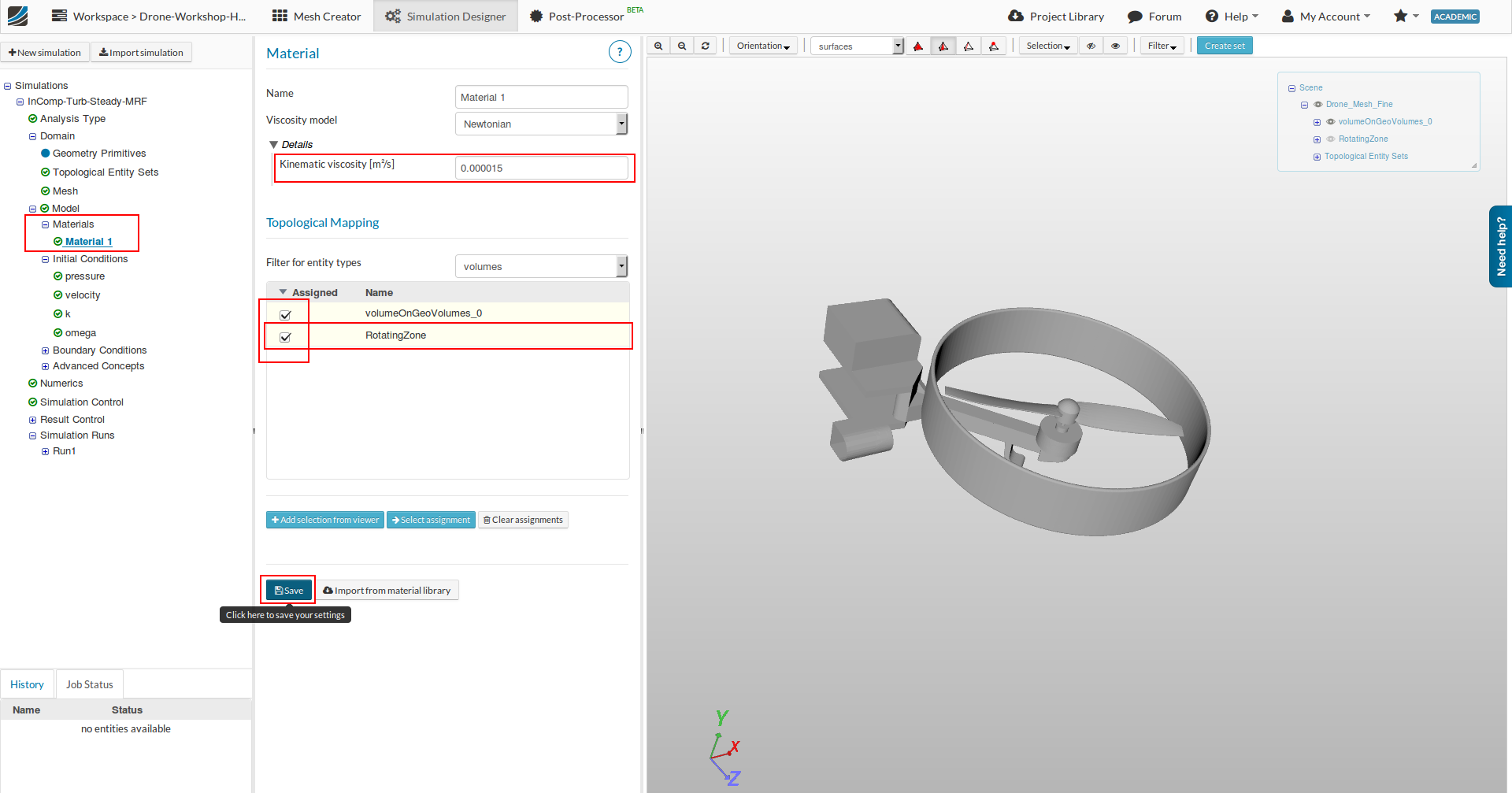
By default, a ‘Material 1’ with properties of Air will be there. Under ‘Topological Mapping’ the 1st entry of ‘volumeOnGeoVolume’ (i.e the main mesh) would be selected by default.
![]() IMPORTANT : Please make sure that you also select ‘RotatingZone’ as shown above ( so that both are selected) and save it for any further Runs. All previous projects and runs will remain valid.
IMPORTANT : Please make sure that you also select ‘RotatingZone’ as shown above ( so that both are selected) and save it for any further Runs. All previous projects and runs will remain valid.
The above TUTORIAL will shortly be updated and show you how to add materials from the library (…its rather easy though ![]() ). Until then, make sure you have made the changes as shown. Ok
). Until then, make sure you have made the changes as shown. Ok
Happy Simulating !
Best,
Ali.
Hi @jigarparekh279
By “4.4mln” I meant 4.4 million elements. Generation time was 993 seconds (according to the mesher’s log), but actually it was more than 17 minutes. It takes the mesher some time to start and finish parallel processes.
However, 9% of a simulation in 120 minutes is really strange. Are you sure you did not miss anything? No misclicks?
What is your End time value and Time step length anyway? Maybe there is your problem. If you set the first one at 2000 [s] and missed to change default step value then you lengthened your simulation by 200 times (!).
How do your convergence plots look like? All below 1e-4?
Hi,
There was a typo in the default value of 0.000001 m2/s. You are correct that the viscosity of Air is about 1e-5 or 1.5e-5 to be more exact.
This has been updated after the platform update yesterday. You will now also have a ‘Material’ sub-tree under ‘Model’ ( please see my latest post below for details).
Nevertheless, you do Not need to do the simulations again and your previous runs / Homework submissions are Accepted ( as the quantitative results are not so relevant ). For further simulation runs, you can now use the default value for Air.
Happy Simulating !
Best,
Ali
Hi @jigarparekh279,
If you have entered the exact values under 'Simulation Control ’ as shown in TUTORIAL at the top, the simulation should take about ( or similar with 16 cores):
Simulation Runtime (min)168 min
Simulation Result size 1,622 megabyte
( given you followed the exact values in meshing aswell to get a meshing time of ‘Finished meshing in = 791.9 s’ and ’ volumes/cells/3D elements:4400346 ')
…these values are from the test runs done by me.
Please check once more you complete simulation setup (…also the new material addition for any new runs you do. see my recent post above or Step-by-Step Tutorial: Homework of Session 1 - Level 2 - #23 by Ali_Arafat)
If you are still having trouble please share your project. Thanks
Best,
Ali.
The End time value and Time step length are correct. Up till now (~500 iterations) residual is approaching 1E-3.
Hi @Ali_Arafat,
Thank you for the timing details. I checked my simulation and couldn’t find anything different from the tutorial.
According the your timing details, I think I should wait for some time as I can see the residuals (although relative) falling and approaching 1E-4 for ~700 iterations.
the inner part of the blade is not meshed at all… this is a fluid dynamics simulation.
@JhonnyFlash If you have a CFD simulation and the fluid does affect the stress on a component why should there be no grid “inside the component”? I think there are some examples out there that have the whole geometry meshed. Maybe @Ali_Arafat can explain a bit more.
this is not the case here.
Hi @jousefm
This particular simulation only involves external flow analysis , so only the surface of the blades are meshed. The surface geometry/mesh is kept rigid and non-deformable. There are stresses on the component due to the fluid but the component is not allowed to deform because of these stresses.
The simulations were the solid also deforms due to fluid stresses are 2 way coupled Fluid Structure Interaction (FSI) type of analysis ( FSIPRO3D Wing Body Pylon Nacelle Model 2 Way Coupled Aeroelastic Vibration - YouTube ). Generally for FSI the " inside of the component" is meshed to calculate the solid deformation and internal stresses.
Here the case is simple, so a mesh inside the component is not required.
But, FSI in the pipeline and would be available on SimScale in the future. ![]()
I hope that answers the question.
Best,
Ali
2 Likes
How could you check in paraview what kind of drag the blades are generating?