Forces along Y axis are indeed in the same direction and you have global lift delivered on the silver plate. However drag will depend on blades shape and you need to know those forces one by one on ONE blade. In my understanding you cannot guess drag knowing only the lift. Correct me if I’m wrong, please.
But the moment about the Y-axis (the axis the prop spins about) is the torque that needs to be applied to the whole propeller to make it spin at that rpm. So it is, by definition, that you can compute input power from torque and rpm. Am I missing something?
Force Plot draws ‘Pressure force Y’ ad this is not a moment and not a torque. For a torque calculation you would need the to know exact point on blade where it should be applied. It is obviously not a blade tip, but depends on blade shape.
When you look up into the graph (last jmayger attached), you see only force along Y axis. That force is ‘felt’ on rotating blades axis, independently of blades count or shape.
Now, if your blades have L/D ratio 2 or L/D ratio 20, the Force graph will be identical. Hence you need to know details of drag and those details will be provide on Forces graph, if you measure them on one blade.
Only then you will be able to calculate the power necessary to deliver to your shaft (and perhaps bad designed blades) to rotate at 2000 rad/s or whatever.
Interesting discussion, by the way, as recently I tried to figure out optimal (wind turbine) rotation speed for energy extraction and messed a bit with Force graph. Without blades separation I was unable to reach any conclusion…
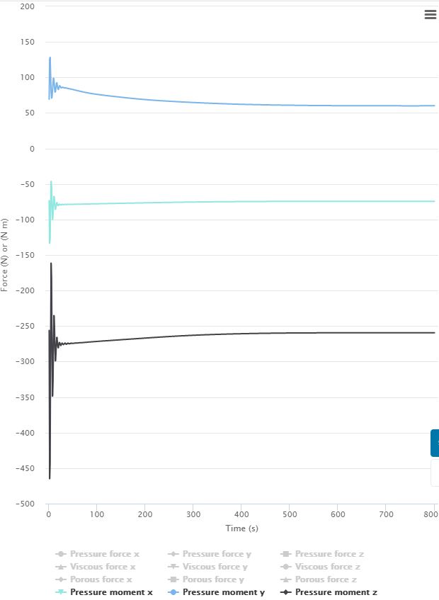
Well, your graph looks good, but the point is that in our discussed case global ‘propeller’ from tutorial, ‘Pression force Y’ is linear, hence it is not a torque. It is a result of torque applied on the shaft. ‘Y’ is normal to the plane on which torque is applied.
We see, in tutorial example, the resulting linear force Y (which will pull up the propeller), but we do not know how big applied torque was.
May I have a look at your example, to better understand your case, please?
That was not an MRF example, I just assumed that there would be no difference using MRF with force and moments results on faces/volumes, whether they are in an MRF or not, so maybe I am missing something regarding MRF’s…
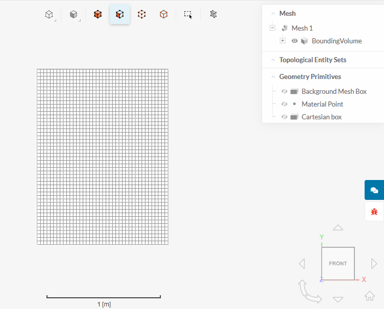
Sorry, another problem just appeared (regarding the meshing process this time). I ran 4-5 simulations smoothly. However, in my new simulation today, the meshing process ends as shown in picture. There is only an element called “BoundingVolume”, instead of “region0” and “Rotation_solid_1” that are the correct result of the meshing process shown in the tutorial. Can it be a bug? After various attempts i can’t figure out where i am getting it wrong. With the exact same parameters the previous meshing attempts went smoothly just until yesterday. The name of my public project is “Drone propeller small”, in case you want to give a look at it. Thank you!

Hi Andrzej & @jarnoldi!
The fix has been released, please check if everything works for you now.
All the best!
Jousef
I confirm that the meshing process is now giving normal results. Thank you very much!