Dear SimScalers,
in this week’s spotlight, we take a look at a finite element simulation of a Roller Bearing by our partner and PowerUser Ben Lewis (@BenLewis ).
Check out our partner: Simulation Software | Engineering AI in the Cloud | SimScale

\underline{\textbf{Introduction & Problem Specification}}
Ben wanted to see how the rollers carry a radial load as they move around the race. To achieve this the rollers don’t actually roll, they are incremented in small steps over time. Another approach will be presented which has been carried out by our Application Engineer @ahmedhussain18 with the same simulation of a Roller Bearing.
This project spotlight is divided into the following parts:
-
Geometry
-
Meshing
-
Simulation
-
Simulation with SimScale
-
Results
\underline{\textbf{Geometry}}
Format: STEP
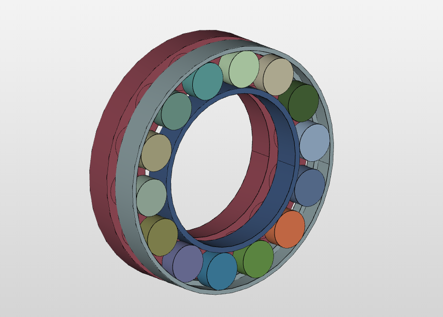
Figure 1: SimScale model
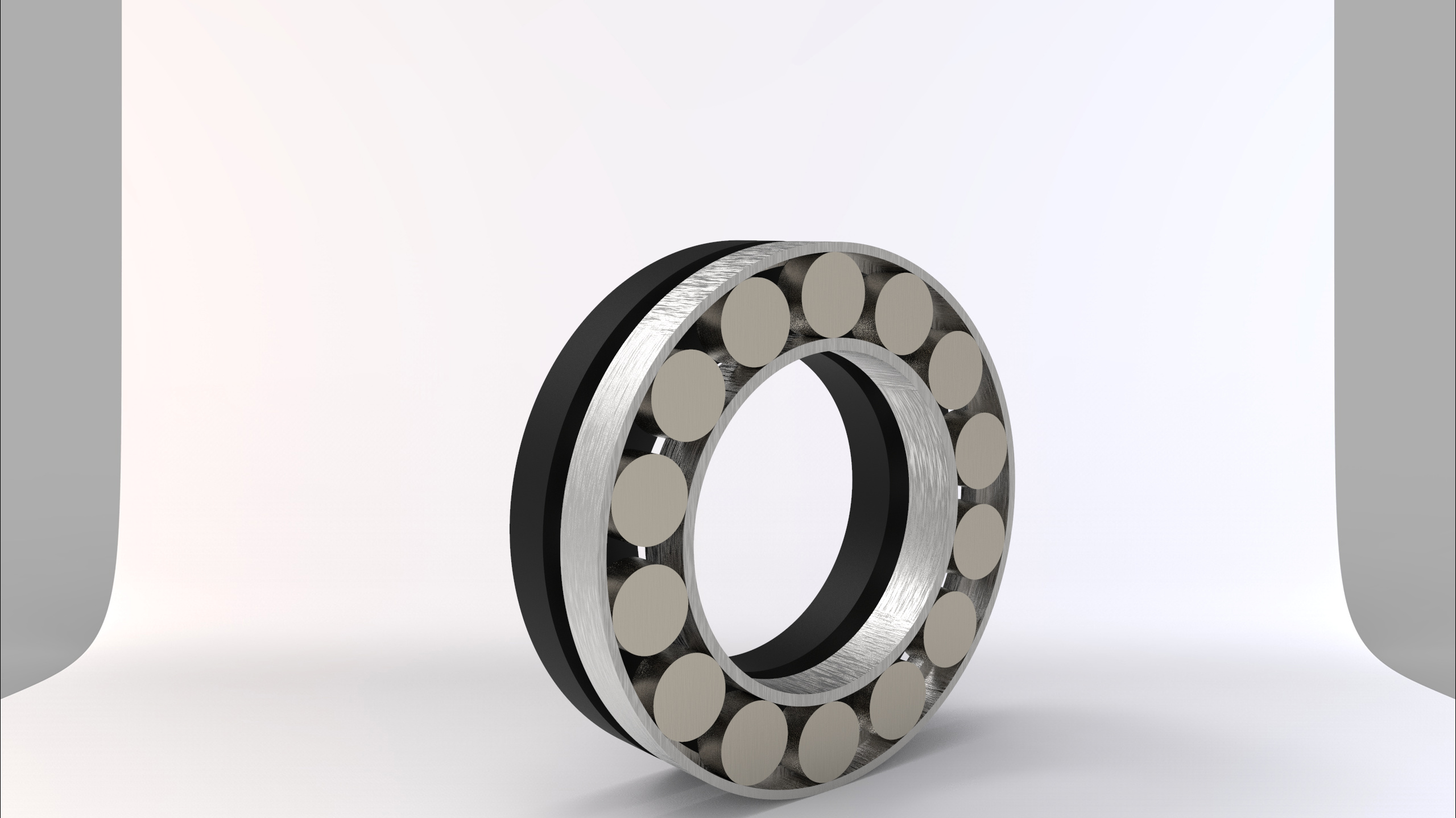
Figure 2: KeyShot rendering
\underline{\textbf{Meshing}}
Type: Tet-dominant
The mesh of the model was executed with the Tet-Dominant all-round meshing algorithm, mostly dedicated to structural mechanics, which can also be used to generate tetrahedral meshes with boundary layers for fluid flow analyses.
Nodes: 131,086
3D elements: 293,239
Contact slave nodes: 2184
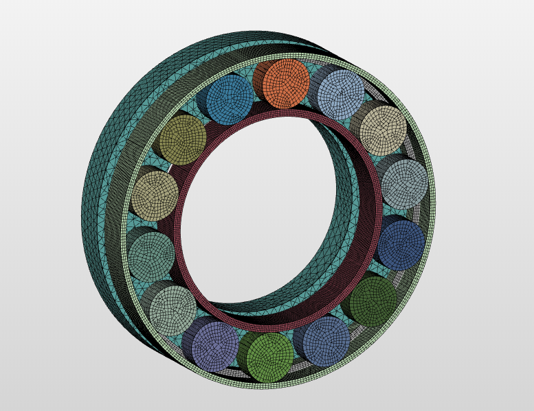
Figure 3: Tet-mesh of the Roller Bearing
\underline{\textbf{Simulation}}
Type: Static Finite-Element Simulation
Nonlinear Analysis: True
\underline{\textbf{Simulation Details}}
Run time: 147 min
Machine: 8 core
Processing time: 19 core hours
Memory: 7.3 GB
\underline{\textbf{Materials}}
\underline{\textbf{Boundary Conditions}}
The setup for the boundary conditions can be found inside the project (link given at the end of the spotlight).
\underline{\textbf{Solution}}
Machine cores: 8
\underline{\textbf{Numerics}}
Numerical settings can be found in the project!
\underline{\textbf{Results}}
\underline{\textbf{Von Mises Stress}}
Figure 5: Animations of the von Mises Stress
\underline{\textbf{SimScale Project}}
To see the simulation setup, please have a look at the project from @BenLewis :
[!!!THIS LINK IS NO LONGER AVAILABLE!!!]
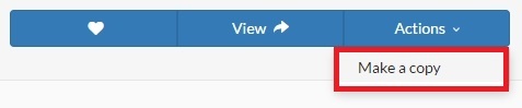
To copy this project into your workspace, simply follow the instructions given in the picture below.
\underline{\textbf{Visit our SimWiki by clicking on the picture}}