Following the advices on one of the latest webinars, i wanted to try out the new standard mesher instead of the hex-dominant parametric mesher.
While the mesh on the car model seems to have gone well, I don’t know how to proceed: the mesh was apparently created only on the model and not on a bounding box, and I don’t know how to set boundary conditions.
I am also confused on how to set the dimensions of the refinement: instead of having to define a level of refinement, I have to set a maximum edge length, but I am not sure what value would be more appropriate; is there any guideline on this or any documentation where I could expand my knowledge?
Using the TET mesher, I am pretty sure that your geometry file still needs to include the domain walls (Background Mesh Box)…
To do this you need to Boolean subtract your car from a BMB sized watertight domain solid (if your CAD software allows this, however, you might need to support your car on a very small string that allows the Boolean subtraction yet the small string will never be meshed in SimScale because it is smaller that your finest refinement level)…
I am pretty sure you will not find the above info at that link…
Hi guys,
Sorry for not getting back to you sooner.
Since I’m working on that project for my University FSAE Team, I am not allowed to share it publicly; I will share it to you in private, Jousef, though.
The Documentation at the current stage does not really explain how to choose sizing or any other parameters yet, and it does also not provide information concerning simulation setup. I am sure you are already working on it!
As Dale said, it looks like my geometry needs to include the fluid domain boundaries; is there any other way to achieve that?
One easy way to extract the flow volume for this geometry using SimScale is by running an enclosure operation, as seen in this video.
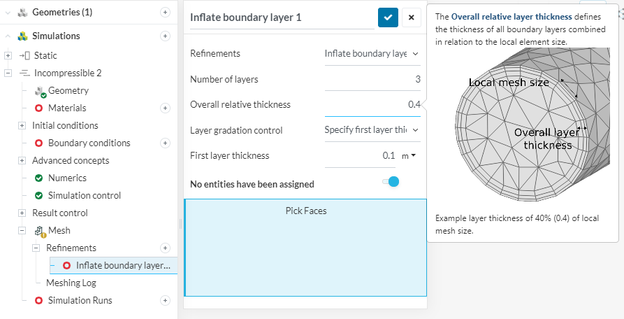
There’s no rule set in stone for element sizing. Generally you want the local surface cells to be small enough to capture the details. Setting a limit to the local cell size assures that you will have a minimum resolution.
Also, keep in mind that the local element size of the surface is related to the inflate boundary layer refinement: