Not to be ornery, but even with the Custom BC, I believe that the BMB needs to be long enough to fully encompass the true/expected wake zone (@dylan stressed to me how important that was to get 1% and more accurate results) which a ‘close in’ rear face would likely not do using the Custom BC.
I have even had a set of results that become stable and when I re-run with exactly the same sim parameters (at least I think they are…), the results diverge, go figure…
yes! This is exactly what I am facing now! If change the BMB size won’t work , I might try re-upload the model and retry everything again. @DaleKramer
I think you need to redo the model now as I suspect the too small MRF zone is the major issue isn’t it @Retsam ?.
I hate to say it but I would even try the ‘new mesh preview’ meshing algorithm (I can’t believe I said that  ) as I find those meshes harder to get stable CFD results from but the meshing is so fast and easy…
But for my other project that has the same size of rotating zone, this problem doesnt exist @DaleKramer
That could have been ‘on the verge’ of results instability, each geometry can react very differently…
Don’t forget golden rules.
- Good geometry file
- Good volume mesh.
- And only then, try a simulation…
If you do not do 1 and 2 well, then your results are questionable even if they become stable…
I tried to change my BMB size now, waiting for the mesh to finish. Later I will run the simulation with 30seconds end time (to save core hour) and see if the problem still exist or not. If it still exists then I will proceed with increasing the rotational zone size @DaleKramer
I really need to stress:
Just trying to give you a least grief road from here…
Re-doing the CAD means that all suggestions so far should be incorporated in your next run, sometimes a step back is worth it…
1 Like
By the way, I notice that you are only using a Force and Moments result that gives you moments split up into pressure and viscous x,y,z components.
You are likely going to use the moment results as a metric to evaluate your geometry changes…
Instead of having to manually (spreadsheet) combine the pressure and viscous moments from the appropriate axes for your comparison…
I suggest that you set up a ‘Hijacked Force and Moment’ coefficient results (one of the methods in that link explains how to set that up) so that the results there would already combine Pressure and Viscous moments for the axis specified in the parameters there…
1 Like
@Retsam method to show if the flow is developing properly will not guarantee that the results will eventually become stable, it is a way to try to figure out convergence issues AFTER you have good geometry and good volume mesh…
Do not bother Dale, I’m only in charge of MY opinions! ![]() In current case, BMB can be small, as 97% of simulation is within an enclosure (special box defined by author of simulation).
In current case, BMB can be small, as 97% of simulation is within an enclosure (special box defined by author of simulation).
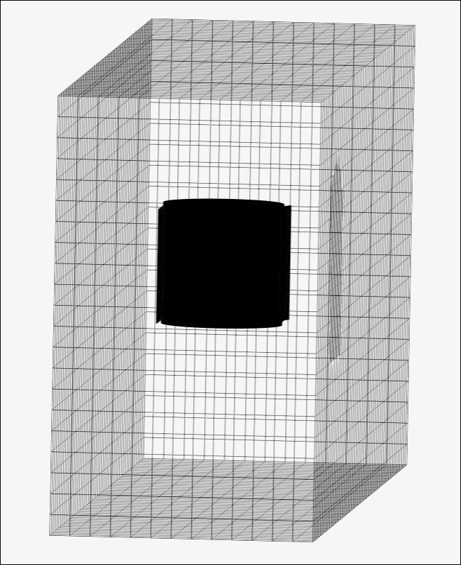
Moreover, MRF should be as small as possible, but should not force extreme refinement of MRF zone itself. In current case, MRF is defined within special enclosure, so it cannot grow beyond (by the way, for internal CFD, MRF can be bigger then the ‘pipe’).
Zero gradient tunnel (instead of slippy walls tunnel), does not cause pressure problem even if it is too small. If you use slip walls, make big BMB, I do agree. As I tested it on my small projects (and I do not need ±1% accuracy), I’m happy with it. ![]()
Ah, yes I agree close rear face is OK if he is only interested in the power output of the blades, but if he is concerned about the different loading this ‘shield’ imparts to the whole structure that the windmill is mounted on then I still think wake area needs inclusion…
Current MRF has portions of blade outside it so I think his next step must be to fix that don’t you ![]()
I also think his interest will be 1% results to see how his changes compare to free standing Savonius…
For the 1% results, I think BMB’s still need ‘regular’ sizing so that the BMB walls are still outside the expected zone of influence of the geometry on the air.
For that reason and as pointed out by @jousefm, the most obvious (but sides are the next obvious) BMB face that needs moving away from the geometry is the inlet face (again for 1% results and assuming wake needs to be considered):
@100067610 , can you tell us if you are interested in high accuracy 1% results and whether you are investigating windmill mounting loads?
I am only interested in the output of the turbine currently. Unfortunately, the result is still not stable. I will try reupload the geometry now. Sigh
1 Like
The rear BMB face then needs only to encompass the wake exiting the shield outlet.
After the first good sim run, you can check velocity vectors near the BMB walls to determine whether the geometry is affecting the air significantly near the wall, if so need to move that BMB face further away…
I would still make the BMB sides and inlet significantly further away.
Again this is very little # of cells and computation core hours cost for the increase of accuracy obtained. (Cells well spent )
1 Like
Ok , I tried increase the size of my mrf zone already , may I know, if that still doesnt solve the convergence problem, what else can i do?
All my other suggestions, starting back at Post 5 ![]()
Like I said, since you redo CAD anyway all my suggestions in this topic now come into play…
Ok sir, i really hope changing the mrf size will help, feeling so stressed and tired now 
That is why, if MRF is not the only culprit here you should try as many other suggestions in this topic as possible in your next sim try (none of which I believe will hinder convergence except maybe switching to TETforCFD mesh, but I present a solution for that here…
There will be more convergence suggestions if you have convergence issues, AFTER we think that you have the best geometry and best volume mesh we can achieve for your needs…
Accurate results from CADA are tedious to obtain ![]()
Check this topic out if you want to see real perseverance to got OK results…
Just so that you can convince me to agree more with your opinion…
Are you telling me that when the geometry would deflect some air particle, which is at quite a distance from the geometry, out of this Custom>Inlet-Outlet face (I sort-of view them as open windows) , that you can be sure the same particle of air will re-enter the window in the same place and at the same speed and direction as it would have been if that custom window was further away than its real path to begin with (I am assuming we are at a place where that particle would get sucked back in from low pressure generated downstream around the geometry)?
If that answer here is YES, I will use very small BMBs with out Custom BC from now on…
That is a mouthful but I hope you get the gist…
In 7 hours I can correct that (I hit some sort of edit limit ![]() )…
)…
To:
I will use very small BMBs with our Custom BC from now on