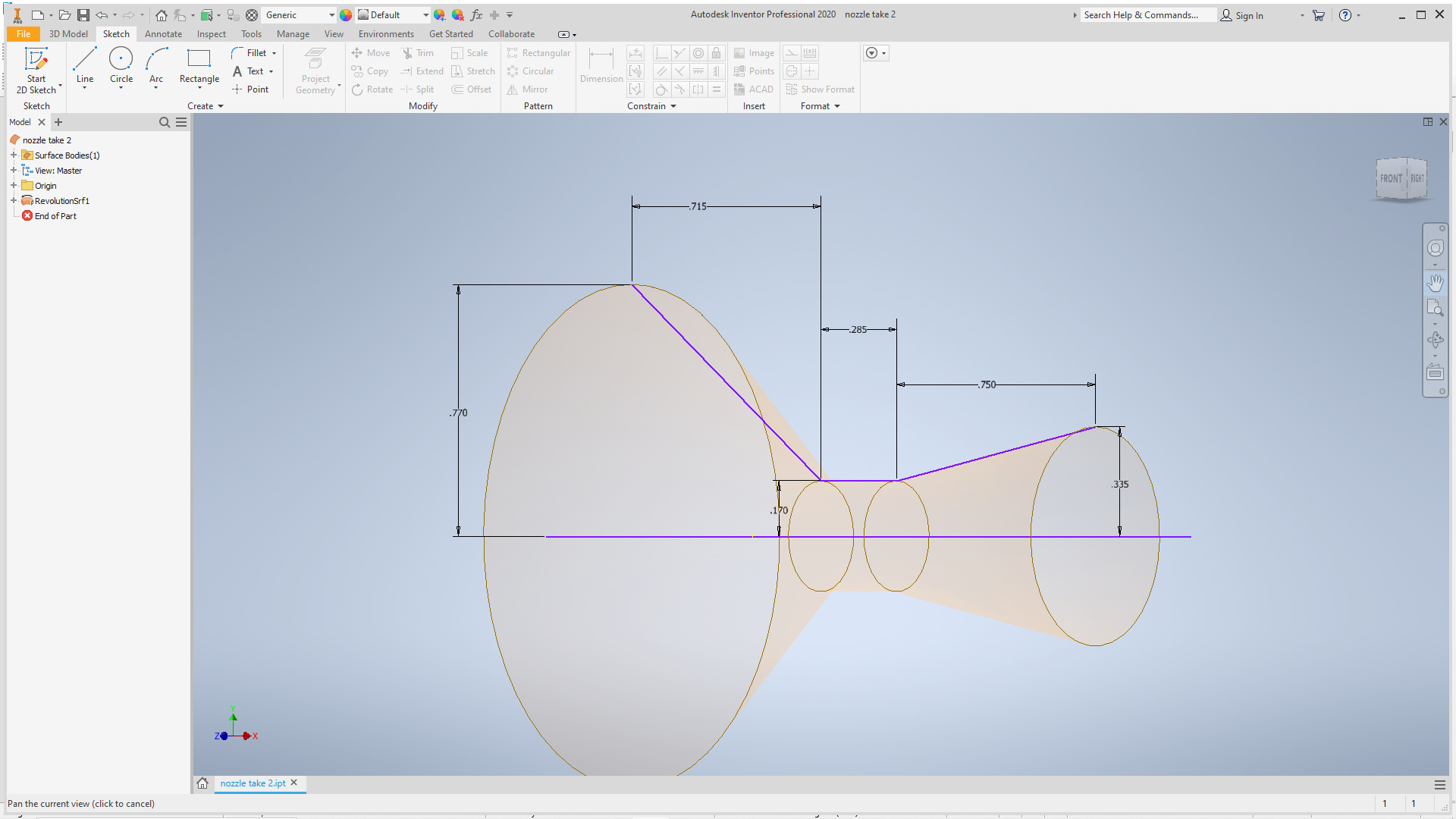
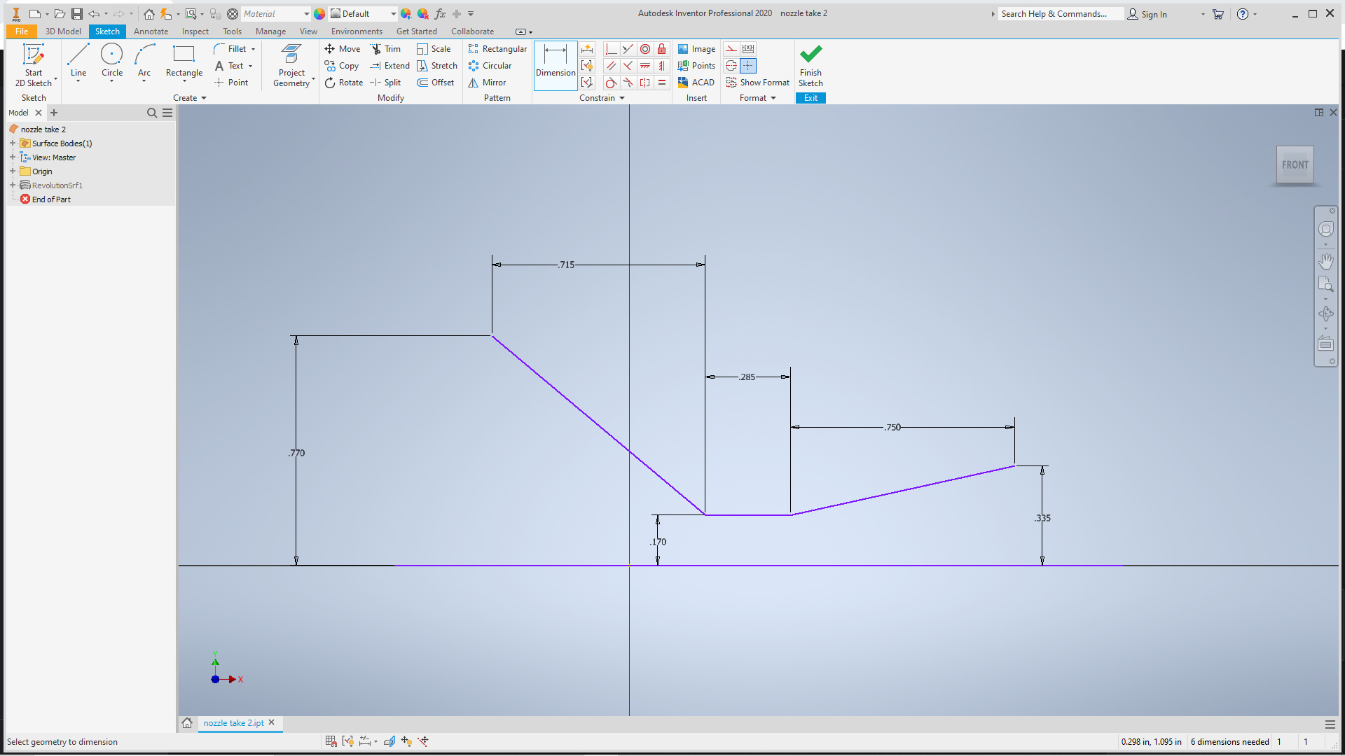
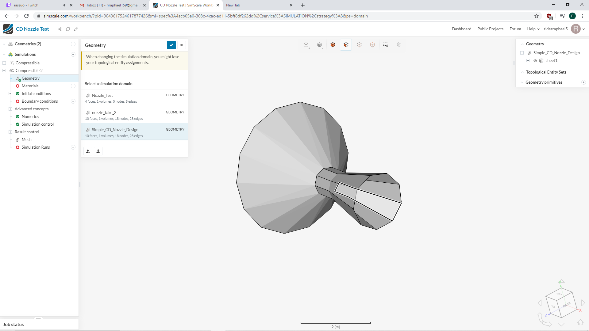
Hey guys, brand new here and trying to get into CFD with a pretty simple project. I came up with a very basic CD Nozzle geometry using essentially just 3 lines on a 2D Sketch and then revolving that around an axis to get the 3D geometry. My problem comes when I try to import that 3D geometry into simscale. I convert the 3D part file from Autodesk into an STL file and get it to upload properly, but the geometry that gets imported is strange in that simscale creates multiple different faces on the nozzle where there is not intended to be any (kind of vague wording I know, but hopefully the pictures help). My questions are how do I refine my geometry in Autodesk so that I can properly import it and get a decent CFD analysis on the nozzle?
Also, this is my first CFD simulation so any advice on how I could perform the analysis would be GREATLY appreciated. Is it as simple as selecting the inlet of the converging section to be a velocity inlet and assigning a value for the velocity (just assuming air for now as the material for simplicity) and then assigning a pressure outlet at the end of the diffuser section? (I guess assume ambient pressure for ideal nozzle case?) Or is it a better approach to do an external flow analysis and have the flow volume pass through the nozzle?
As a little background, I actually milled out a nozzle with almost the exact geometry of the part file that I am using for this analysis and tested it in a Paraffin/Nitrous Oxide Hybrid Rocket and it performed very well so I am just trying to use the CFD analysis to verify the results I got from my static firing. Additionally, if there are any other files you need or clarification, let me know and I’ll try to provide it! Again, I am brand new at this so I apologize if my questions are kind of vague or it seems like I don’t know what I’m talking about (because I don’t!  )
)
Hi there!
First of all you need to make sure that your geometry is closed (watertight) - feel free to check out the public projects library and look for “nozzle” and you will see other simulations tackling this problem as well.
Let us know if you have any questions.
Jousef
Hey!
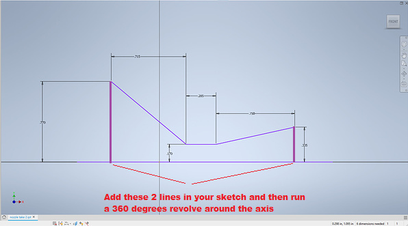
Since you already have the dimensions of the nozzle, I believe the best approach would be to generate the flow region locally in your CAD software. So, taking one of the images that you posted, you just have to add these 2 purple lines:
The result would be something like this: https://www.simscale.com/workbench/?pid=8412857534466666932&mi=geometry%3A12&mt=GEOMETRY
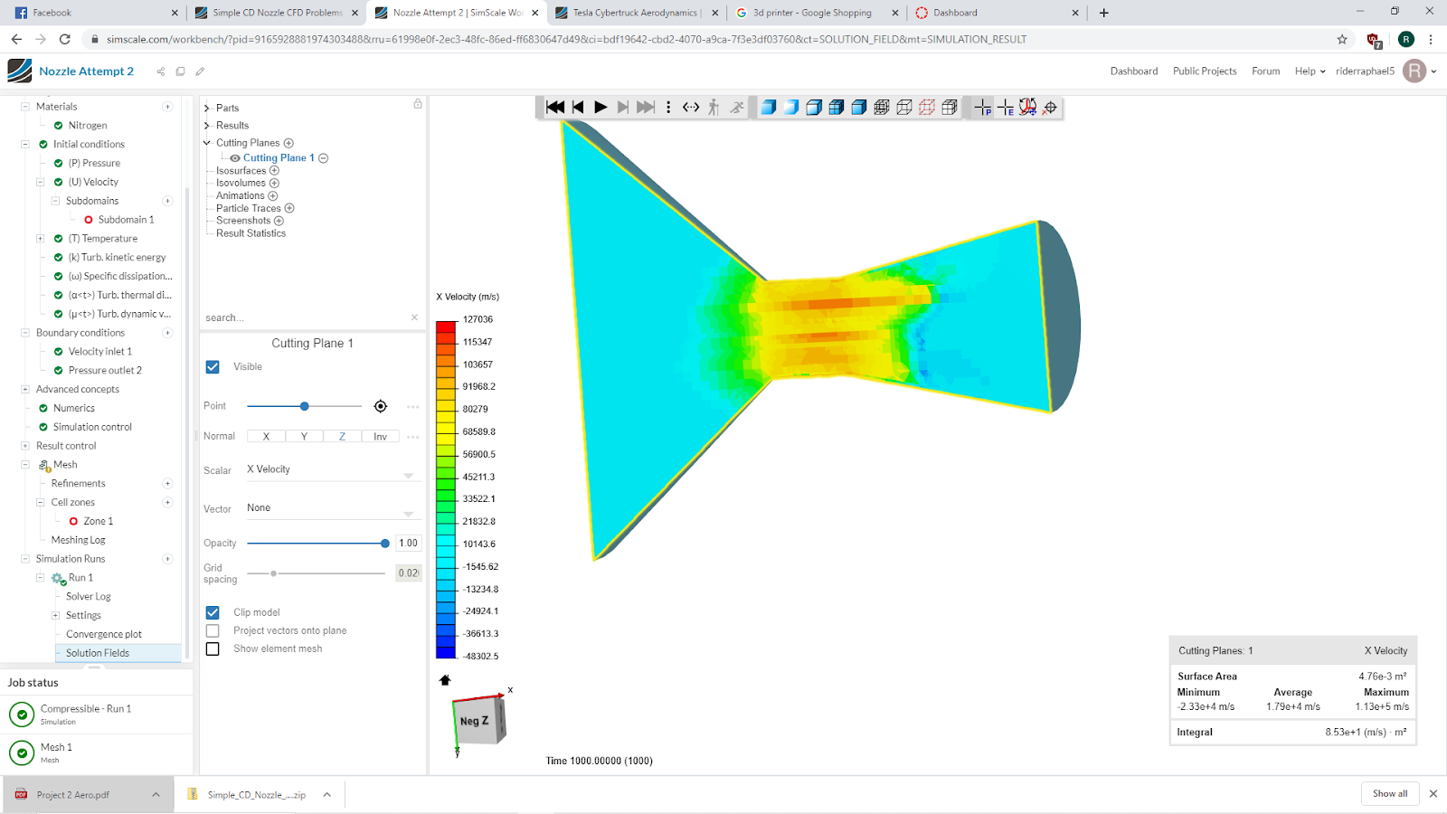
Thank you guys for your help! After double checking my geometry and generating the flow region within my CAD program, I managed to get the mesh to generate and the simulation to run without any errors. This brings up another question I have now though over some of the results that I got.
From what I would expect, shouldn’t the change in velocity be continuous from the inlet of the converging section to the throat? It seems that I am only getting changes as the flow approaches the throat. Secondly, the velocities that it is recording are very high, is this a result of the initial conditions I provided? (Air as the material at 400C and 100 m/s at the velocity inlet and ambient pressure at the outlet of the diffuser) and finally, this could just be because the nozzle is not properly choked for air flowing through, but it seems like the flow does what I would expect for a CD nozzle in that it accelerates up to the throat, but instead of continuing to accelerate it reverts back to the inlet velocity at the exit plane. Any ideas on why that could be other than the nozzle I have is not choked (M =/= 1 at the throat) or that my initial conditions I set are causing problems?
Thank you guys again for your help; this is proving to be an amazing learning experience for me as I look to get more into CFD analysis.
I actually see a thread where someone else had this problem with the unexpected high velocities and that checking the option “Potential foam initialization” seemed to resolve the issue, but I am not seeing the option under my simulation control; is it possible to do this for compressible flow analysis?
Hey there!
Have you had a look at this validation case already: Laval Nozzle - also you could have used rotational symmetry to your benefit in your case.
Cheers,
Jousef