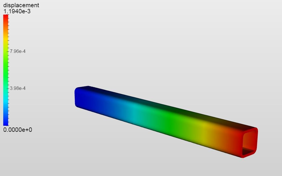
I have made a simple Bending Analysis for a struktural tube 50x50x5 with 500mm length. The tube is fixed on one side and bears a load of 100N on the other side (at the edge - nodal load). It results to a displacement of 1.1940e-3 mm.
The same analysis runed on other software and simple calculation sheets gives a displacement of approximately 0,074mm. I think there is a significant difference. I wanted to know if I am making something wrong or this difference lies in the normal tollerance field?
First of all a hint regarding the units of your result. SimScale handles the geometry in meters which means that in your case the result is 1.194e-3 m, which is a larger displacement than the 7.4e-5 m that you were expecting. So where does that result from?
You applied your load of 100 N at the end of the beam as a nodal load. In fact a nodal load adds a force with its full magnitude to every node lying on the assigned entity (in this case I guess you chose the face at the end of the beam). It is therefore not appropriate for the application of distributed forces as the resulting force depends in that case on the mesh fineness and the loading would not be correct at the boundaries of the entity. So in your case this boundary conditions type would be only fitting if you would apply the load on a single noad (e.g. in the middle of the lower edge). You can find the information also in our documentation:
What, I guess, you actually want to apply is a resulting force of 100 N at the end of the beam. This can be done by a force boundary condition.
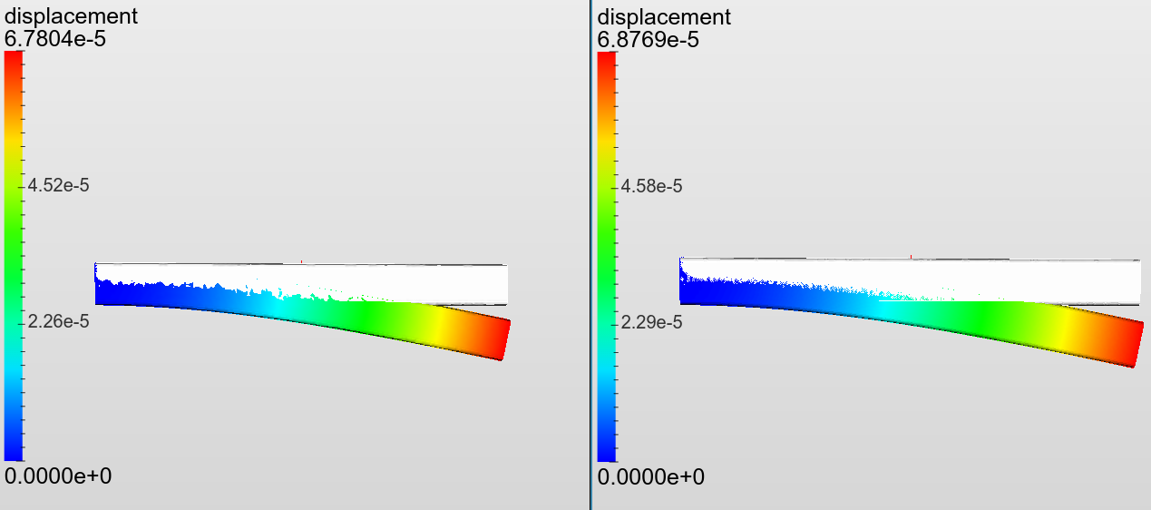
Please use the Static analysis (advanced) analysis type in order to use it. This boundary condition distributes the resulting force according to the edge lenth or the surface area on an assigned entity. I did not know your material parameters and the fillet radius of the geometry but the results are close to what you expected at aroung 0.068 mm (the left result is from a coarse first order mesh, the right one from a 2nd order mesh, the displacment is scaled by a factor of 1000). It would be great if you could tell us what you got for your setup after running with the new bcs.
You can also have a look at our beam validaton examples in the project library:
I understand that without the documentation the nodal load assignment might be confusing. We will consider removing faces and edges as possible assignment options from this boundary condition type. Please keep us updated
I thought that by choosing all the nodes on the side where the force apply, it would result in a distributed load. Wrong…!
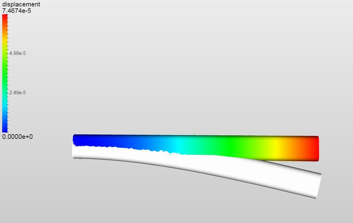
By choosing the entire face and applying a “Force” I receive the right displacement.