Most of of the structural simulation performed for commercial use requires high computing power and memory capacity. Therefore, knowing how to do a simulation more efficiently comes very handy. One method of efficiently using finite element (FE) modelling is to exploit the planes of symmetry in an assembly or a part being analysed.
The existence of a symmetric plane with respect to which geometry, constraints and loads are symmetric is perquisite for using this boundary condition.
First, we will go through how this is implemented using displacement boundary conditions and afterwards, we will learn how can we use symmetry boundary conditions in our platform to achieve the same. Finally, we will learn how to use Cyclic Symmetry Conditions to reduce axisymmetric problems.
Applying Symmetry Boundary Conditions####
Method 1 : Using Displacement Boundary Conditions for Symmetry
In solid mechanics, the general rule for a symmetry displacement condition is that the displacement vector component perpendicular to the plane is zero and the rotational vector components parallel to the plane are zero. So, using displacement boundary conditions to apply symmetric conditions is to employ the rule mentioned above.
Let’s consider a simple two dimensional solid mechanics problem for better understanding.
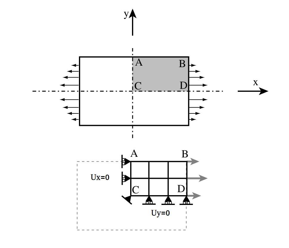
From the figure, it is clear that X axis and Y axis are the lines of symmetry for the given problem and our intuition tells us there won’t be any displacement normal to the line of symmetry. Therefore, the problem is reduced by cutting the geometry along the X and Y axis and applying zero displacement normal to these lines.
In three dimensional problem, symmetry lines are replaced by symmetry planes.
Let’s consider a static analysis on a skate board where load is applied at the centre. Clearly, it has two planes of symmetry, marked in red lines.
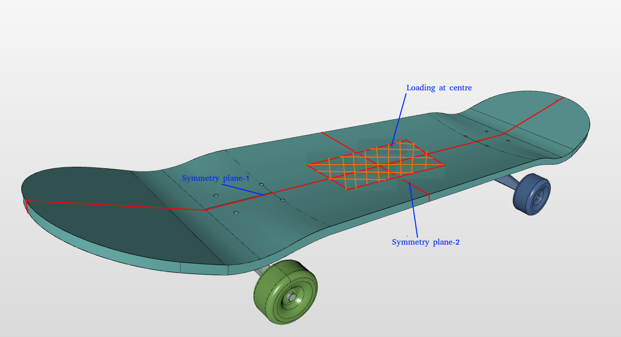
The model can be reduced by taking a quarter section of the model cut along the planes of symmetry as shown in the figure below. In this example, XY and YZ are the symmetry planes and hence DOF perpendicular to the planes, z and x are constrained respectively.
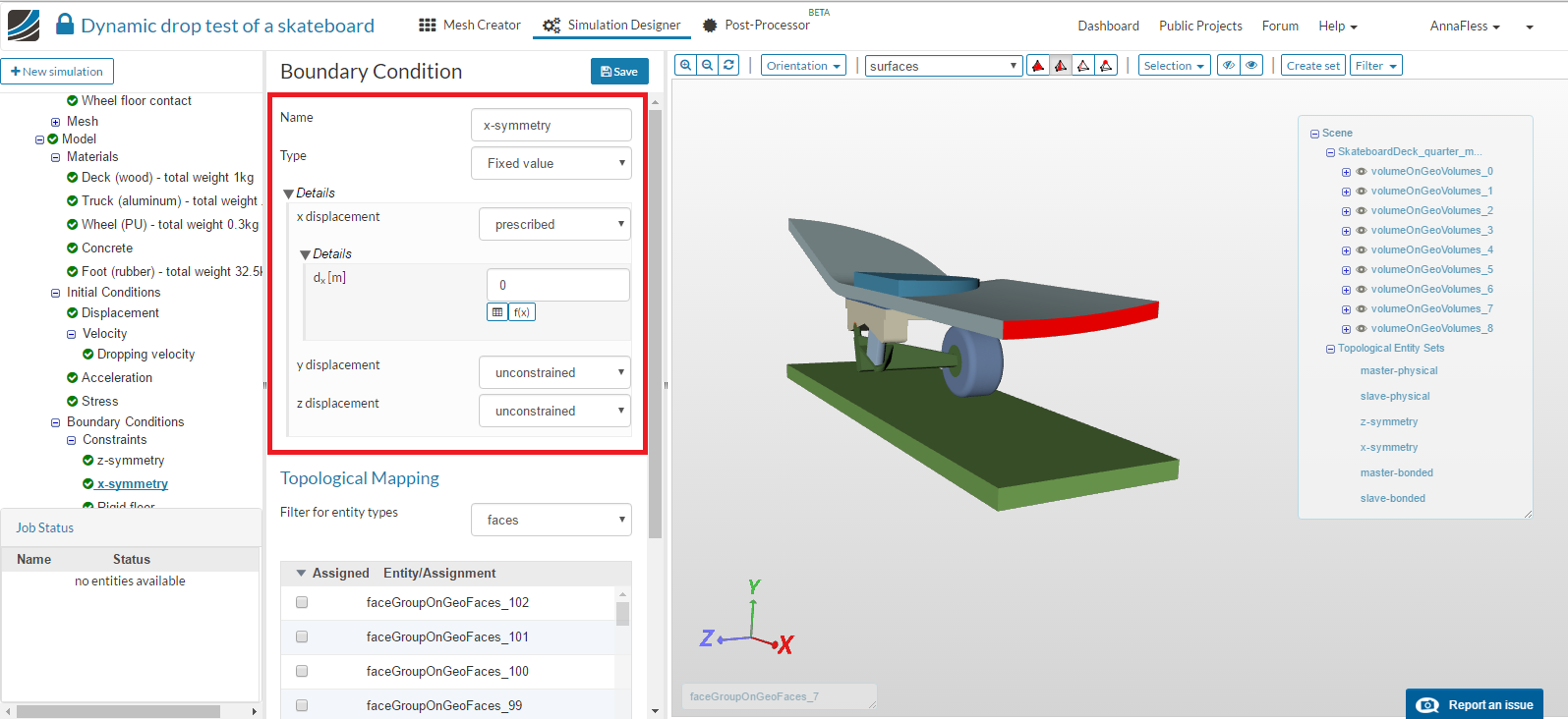
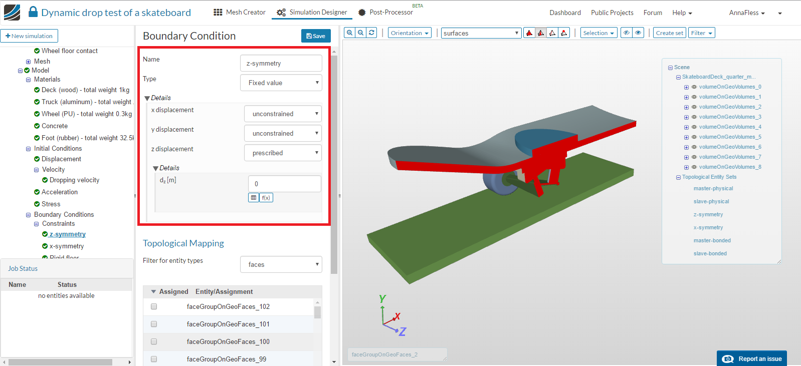
Go to Constraint under the Boundary conditions and click on New to create a new boundary condition. Select Fixed value for the type and choose faces where symmetry conditions need to be applied and impose 0 displacement in the direction normal to the symmetry plane.
X-symmetry
Z-symmetry
**Method 2: Using 'Symmetry Plane' Boundary Conditions type for Symmetry in Simscale**
In SimScale, if the planes are not aligned in the direction of global coordinate axis then using symmetry boundary conditions is very useful. Once the symmetric planes are identified and the model is cut along these planes in a native CAD tool, using this method to apply symmetry conditions is very straight forward.
Let’s consider the same skate board problem discussed in earlier example. In this example, we will try to apply symmetry conditions using Symmetry plane option available in Simscale

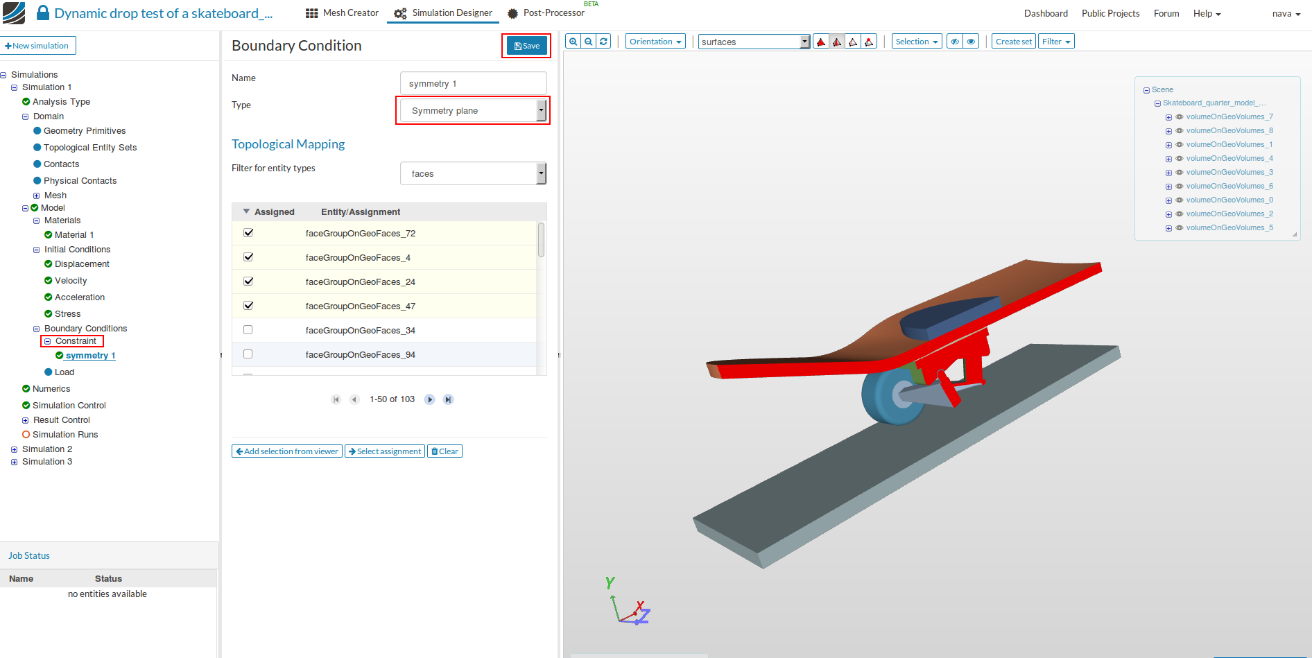
Go to Constraint under the Boundary conditions and click on New to create a new boundary condition. Select Symmetry plane for the type and choose faces where symmetry conditions need to be applied and then Save.
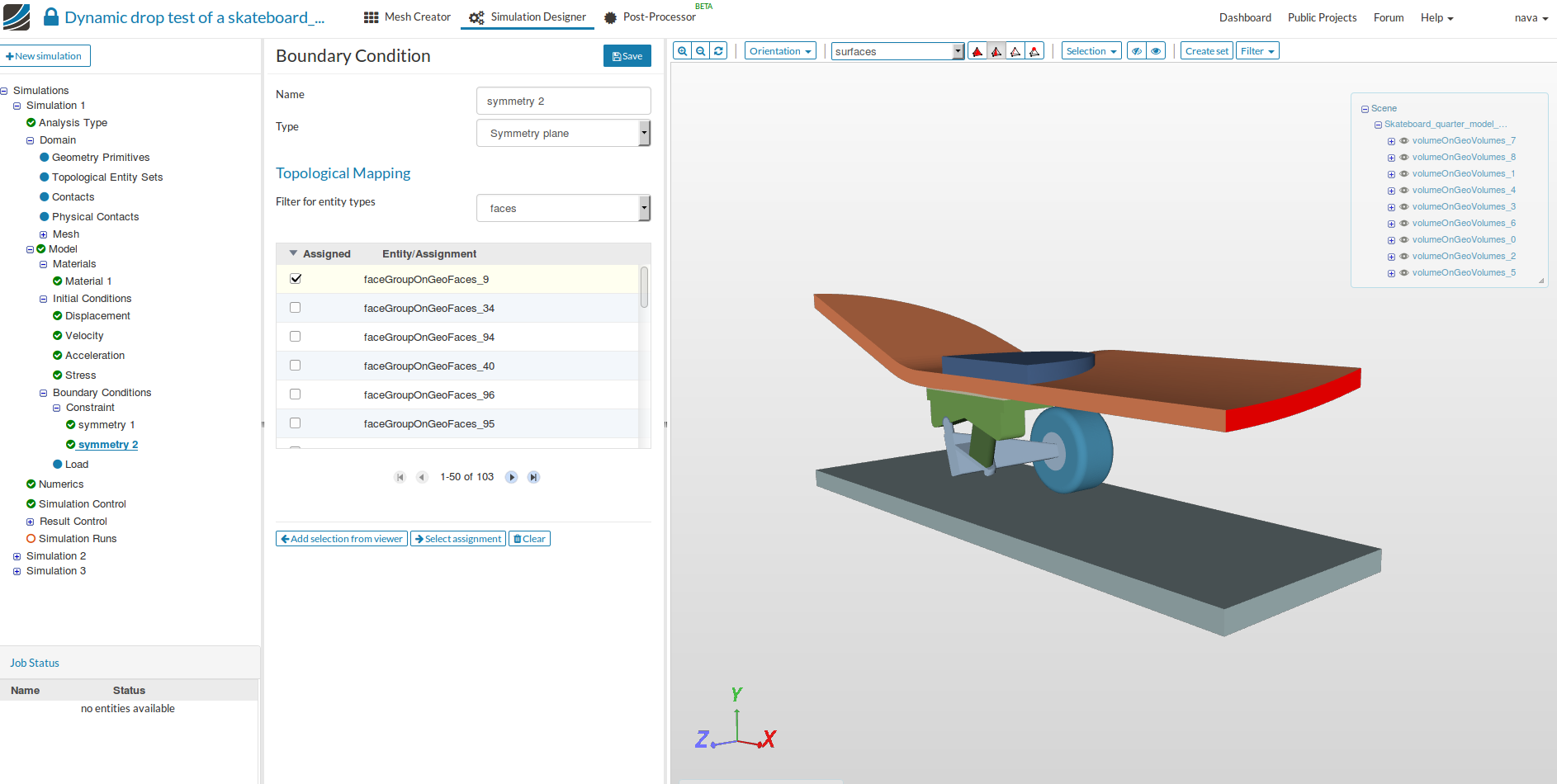
Same steps are followed for the other symmetry plane.
**IMPORTANT NOTE**: It is preferable to use displacement boundary conditions (method 1) to apply symmetry, as using the _symmetry plane_ boundary condition type (method 2) directly might result in an over constrained system when the nodes in the symmetry planes are also constrained by some other boundary conditions or are used as slave entity in physical contact. In that case, align the symmetry plane with the coordinate axis in a CAD software and apply symmetry conditions by fixing the DOF perpendicular to the symmetry plane.
Applying Circular Symmetry
There are several problems which are axisymmetric ( symmetric about axis) in nature, for example, pressure applied inside a cylinder, shrink fitting two cylinders etc. These problems can be reduced by considering a small sector of the geometry( say 1deg) and applying symmetry and circular symmetry conditions.
Let us consider an example of cylindrical pressure vessel with uniform thickness. We can clearly identify a set of two perpendicular planes about which the problem is symmetric.
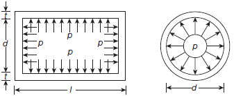
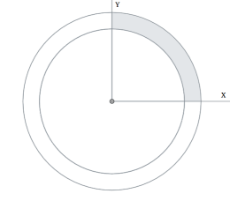
This model can be further reduced by cutting a sector starting from XZ or YZ plane.
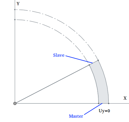
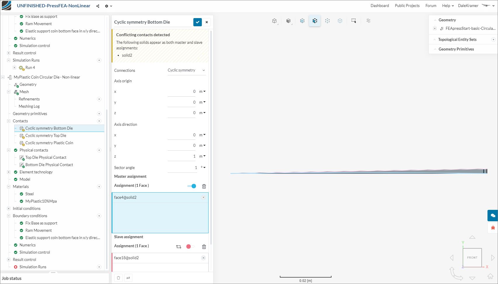
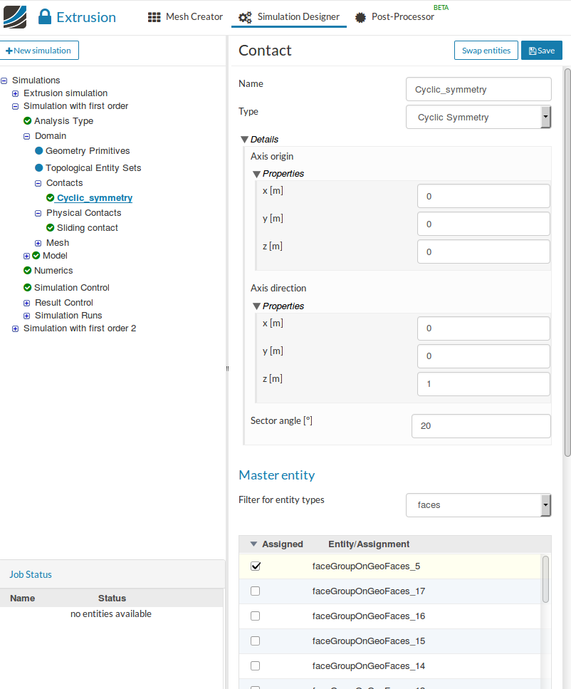
Since XZ and YZ are planes of symmetry, therefore, the DOF perpendicular to the plane should be set to zero. For applying circular symmetry, go to Contacts and then New , specify the Axis origin (0,0,0) , the Axis direction ( z-axis), select the Master ( faces where symmetry is applied) and Slave faces (faces where circular symmetry is applied) and then finally Save.
Note: Although the choice of symmetry planes is arbitrary, it is convenient to choose XZ and YZ as symmetry planes since we can apply symmetric boundary conditions by setting perpendicular DOF (Uy or Ux) to be zero. Otherwise, we have to use symmetry boundary conditions which might result in an over constrained system.