Static Non-linear FEA simulation errors - Newton convergence could not be reached

I am trying to take a plastic coin and press it between 2 steel plates so that I can have a thinner and larger diameter plastic coin (about 25 times thinner).

I have reviewed stretch forming projects but have not found any that help with my squeezing project.

Right now I am chasing my tail a bit and wonder if anyone can see any obvious setup errors… or tell me if I am even on the right track…

Here is the last failed sim run.

Dale

Hi @DaleKramer,
I can spot a few things that could be improved:

  • your movement is defined in positive Z-direction, which won’t squeeze the coin, but lift the plate :wink:
  • you define a physical contact between the coin base and the lower plate, but also fix the coin base with a constraint - this will probably over-constrain the system, but at least the contact is superfluous . Choose either the contact or the constraint
  • if you remove the bottom coin constraint than you only have the coin constrianed by contacts and this does not restrict the movement at all in X and Y directions (imagine you use two plates of ice - the coin will definitely slip away). I would use a small elastic support on the side of the coin
  • your model is perfectly symmetric, so you could save some core-hours (and headaches regarding the proper constraint on the coin sideways movement) by using a quarter model

Hope this gets you further!
Best,
Richard

2 Likes

Wow, I’m blaming that on the 1 am to 4 am time frame of project development :wink:

I tried initially without the x/y constraint on the bottom coin face but got errors that lead me to constrain it too and after constraining bottom coin face in x/y then the errors led elsewhere…

Aha, elastic support :bulb: the coin, will do :slight_smile:

Yep, will get to symmetry eventually but I had issues with the 1/4 model on that airship FEA project (where the constraints at symmetry planes would not seem to let the envelope expand realistically) and I did not want to go there again until I got something working, besides this FEA stuff is so much quicker than the CFD stuff I started my SimScaling with :smile:

Thanks Richard as always :clap:

EDIT 1:

So I tried:
1. Fixed ram movement direction (not responsible for the error and I think I would have quickly seen the error in my ways when a sim was completed and ram move up :wink: )
2. Added x/y elastic support to bottom coin face (and removed fixed constraint an that face)

@rszoeke here is the run after those changes (I had to cancel it as Solver Log never appeared after 33 core hours), any ideas :question:

I am working on symmetry as you know but still should work as is :frowning:

Here is interesting quote from @nava which may have been my problem with my airship FEA :

EDIT 2:

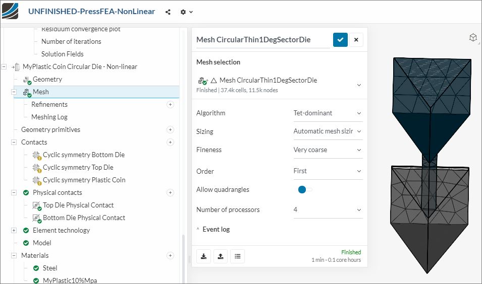
So I have been able to add Cyclic symmetry to a circular die setup and it looks great but still errors in simulation and I am lost on a fix, any ideas on this separate sim and run error and fix :question:

Edit 3 - re edit 2:

This is a way out there thought but, any chance this geometry display ‘bug’ could be an issue. The geometry shows a curved face (not curved in Rhino):
**

**

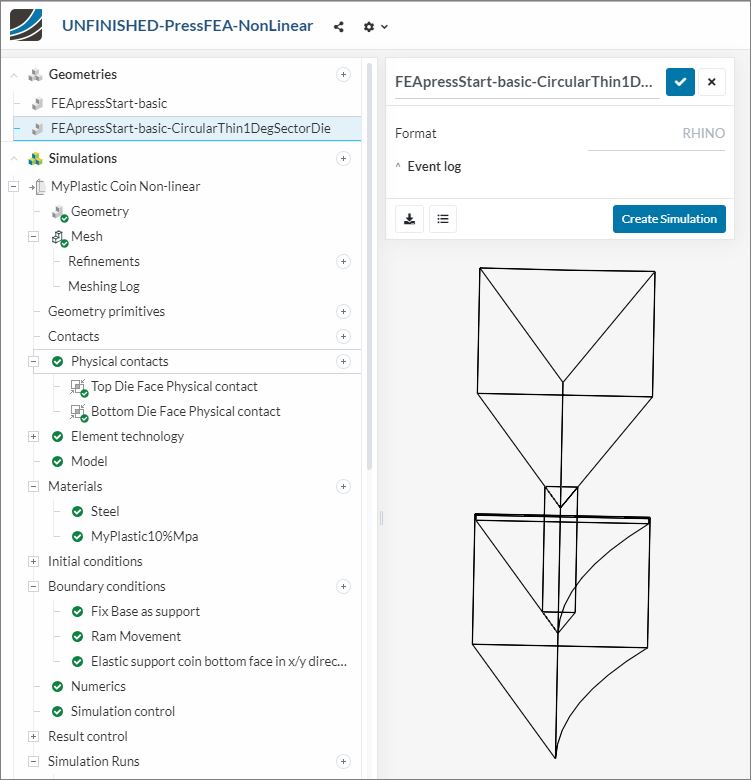
BUT the mesh from that geometry is straight again:

@rszoeke are you getting notified every time I edit that above post since @rszoeke is in that post :question:

No, I am only notified on an answer to a thread/category I follow or when I am mentioned in an initial message.
Updates of the message do not trigger a notification.

1 Like

@jousefm Would it be better if I showed my progress in separate sequential posts if no-one has responded between my edits?

@DaleKramer,
regarding the run for the full model, I think the scale of the movement is too large. You seem to want to apply a 12mm movement, but the coin seems only 1.2mm thick?

Regarding the cyclic symmetry: the setup is unfortunately not so straight-forward. Your system is basically over-constraint. The slave nodes of the cyclic symmetry condition are tied in normal direction already to the master elements on the opposite side. If you add a fixed value constraint on top there, you need to leave the normal direction free, otherwise you would constrain them twice. I can set up a working model later, but have no time at the moment. Please also make sure that the master and slave faces are correctly assigned based on the direction of the axis of rotation. You might find some useful information here: Contacts & Interfaces in Solid Mechanics and CHT | SimScale.

Best,
Richard

1 Like

Sorry for magnitude of steps for ram movement error, another fumble I will blame on the late night project :wink: I should have seen that but just I’m learning formulas etc for movements etc…

Will do on the cyclic symmetry, thanks for suggestions and link :slight_smile:

Hi @DaleKramer,

I changed the loading error and your model ran and converged for about .25 of the total time. Do you have any nonlinear material properties for the plastic your using? This may be part of the problem of why it cannot converge once is compressed the dist too much.

Christopher

3 Likes

Yes, I too just saw that my ‘MyPlastic10%Mpa’ had reverted to linear elastic, I know I had it as plastic with a table. Not sure hoe the table was lost and behaviour changed???

I will put them back to plastic with table now… Thanks…

EDIT 1: Fixed that now but not too sure if I have a good stress/strain curve yet (I am making some assumptions of my plastic at high temperature)

EDIT 2: Ok finally got some action on my full model, this animation shows coin expanding but nowhere’s near big enough, it should go out to almost the corner triangle squeeze depth stop, here is pic :slight_smile: :

I likely need to play with my stress/strain curve… I’ll do that after I get the low overhead Cyclic symmetry version working :wink:

HOWEVER, still have unknown issues with the Cyclic symmetry version , any ideas :question:

@rszoeke In the Documentation link you provided I found this quote WRT cyclic symmetry condition:

" This is a linear constraint, so no large rotations or large deformations are allowed in the proximity of cyclic symmetry boundaries. "

Would this not seem to say I likely should not use Cyclic symmetry since my plastic coin deforms along a boundary of all my Cyclic symmetry contacts :question:

Hey Dale,

We can keep everything tidy and organized by keeping it in one place :slight_smile:

So my edit method is OK then (even after there are replies to a post I am editing) :question:

Hi @DaleKramer,

I am not sure what’s happening yet, but if you look at the mesh of the disk at the last time step, you can see the elements around the edge are elongated and growing the disk. The elements in the middle have not changed shape so the are not squishing correctly. This explains why your not seeing the larger change of shape you are expecting.

I’ll keep looking into it. I do know once you start deforming the elements too much the accuracy will go down and the convergence will be more difficult but I don’t think that is the problem yet.

Christopher

2 Likes

WOW, I will gratefully accept your help on this :smile: , I am such an FEA newbie, but I try :wink:

Sure. If the threads are longer you can also note in the recent posts that edits have been made - that’s up to you :slight_smile:

1 Like

Sorry, I just had to post this :smiley:

Crêpes go to the #cooking section of our Slack channel Dale! :wink:

1 Like

Nice that you made some significant progress @DaleKramer!

As you added an elastic support to the lower surface of the coin, it actually does not deform symmetrically and the lower surface remains almost undeformed. I would probably use either both surfaces or the side face - btw. you can also use an orthotropic elastic support stiffness, and for example put a close to zero value in normal direction.

Wrt the small deformation limitation I would say in your case it should be fine as the normals of the cyclic symmetry plane do not change.

Your coin is also smaller than expected as you got some (relative to the final thickness) large contact penetration. You can try to increase the penalty factor or switch to a lagrangian contact to reduce the contact penetration.

Best,
Richard

1 Like

I do not see Lagrangien options for contact type in the new WB.
Nothing in Numerics either…
I don’t see in any Documentation how to select a Lagrangien contact, I would like to try it…
I did see this but not sure what it means:

The contact solution method has to be chosen in a global sense in a simulation setup. Of course you can define different properties for different contact pairs, but it is not possible to switch between for example penalty and lagrangian contact.