Hi,
I’m trying to model some high-power linear MOSFETs dissipating 1500W on a forced-air cooled heat-sink. That works fine in concept but to make it match reality I need to ensure my MOSFET model is accurate so the heat generated in the silicon die transfers accurately to the casing face mated to the heatsink. The manufacturer refuses to give any information on the internal construction of the MOSFET; the only information provided is a thermal resistance of 0.12K/W from junction to case (Tjc), specified at a power dissipation of 1000W, a junction temperature of 150degC and a heatsink temperature of 25degC (i.e. the JEDEC specification for Tjc based on a theoretical infinite heatsink).
To try and model the MOSFET’s PLUSPak247 construction thermally I have ‘guesstimated’ it as a 10 x 10 x 0.2mm silicon die on an 10 x 10 x 0.2mm thick ‘bonding material’ centrally mounted on a 21 x 16 x 2mm copper base, totally covered in a 5mm thick epoxy casing (shown below without epoxy case.). I ‘placed’ this MOSFET on a 1m x 1m x 100mm ‘infinite’ heatsink of conductivity 1e +6 W/m.K and specific heat of 1J/kg.K naturally convected in a 2 x 2 x 2m enclosure of air at 25degC.
Using the same ‘infinite’ material for the bonding I ran a CHT simulation at 10W and compared the maximum chip temperature to the maximum heatsink temperature (Tc - Th)/W which gave me (300.5 - 300.1)/10, a Tjc of 0.04K/W. I then experimented with different thermal conductivity for the bond, eventually settling on 30 W/m.K which gives a Tjc of 0.12K/W. I then re-ran the simulation at 1000W which gives a Tjc of 0.123K/W, albeit with a heatsink max temp of 335.8K and a chip of 460.1K giving a Tjc of (460.1-335.8)/1000 of 0.124K/W. Although this gives a heatsink temp higher than the 25degC of the JEDEC spec it’s linearly consistent (62.6 → 25 gives 186.9 ->149.3degC) and reflects the non-infinite nature of the heatsink at the higher power, which I’m sure could be addressed by making it bigger.
So, my question is: is this a valid approach? Is it a ‘good enough’ model for the MOSFET to make my planned simulation of 8 devices at 200W each on a single heatsink accurate enough to have confidence in spending £200 on parts?
So usually we model components where we don’t have the exact geometrical representation but the contact resistance values given with Thermal resistance networks (Documentation). Actually we also prefer in most situations to use these compact models even if the geometry is given in detail just for the simplicity and good approximation they give. This feature is not yet available in the new CHT v2.0 but will be soon added as well.
So my main question for you would be: Are you avoiding Thermal resistance networks here intentionally as you are really looking for a better physical representation of the actual MOSFET as you pointed out that the thermal resistance value is derived from a certain assumption (e.g. in your case 1000 W power and the infinite heatsink scenario) or couldn’t you find it in the CHT v2.0 setup?
Thanks for your response . I’m not wedded to my approach, it just seemed the simplest way forward. I am familiar with thermal networks but these are 1-dimensional models and I wasn’t sure how well they represented reality; I hadn’t seen the information you linked to (it doesn’t appear yet under Advanced concepts in my CHT2.0). Even if I had, I’m not sure how to define the resistances sideways and up through the epoxy casing given the 0.12K/W value is junction to mating surface and there is no spec for the other faces. Your thoughts?
An added thought: one reason I took this approach is that the connection of the pins to the PCB is a significant thermal path. Although not in this first iteration the final simulation will include the PCB with tracks carrying between 50 and 100A and there will be some substantial amounts of copper attached specifically to the centre pin (as well as the thermal effect of the current raising PCB track temperature by 10 - 15degC).
so usually if there is just one value given (e.g. junction to board resistance), it means that the rest of the resistance values can be almost neglected. Otherwise sometimes there are multiple resistances provided by suppliers e.g. additionally junction to case (top) resistance or even to the sides. In most cases at least the side resistances are neglected though.
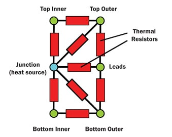
In theory of course the networks can be as complex as defined by JEDEC:
To my knowledge the whole point of those compact thermal models though is that they actually represent the actual physics in many cases much better than trying to resolve these parts geometrically in detail. I am dealing mostly with simple chips e.g. LED COB or single chips where those models are very valid. /so I am not sure it is the best approach in your case, but as you don’t have the geometrical details anyways, I think it’s worth a try.
They should now be available to you as the release just happened yesterday by coincidence
They don’t appear in CHT 1.0 unless you have radiation turned off… so you can model a transistor on a heatsink using thermal resistances as long as you don’t model the effect of radiation from the heatsink as well, which seems counter-intuitive. They still, at the time of writing (13:21GMT on 23/Jan) don’t appear in CHT2.0 yet.
I can confirm that TRNs are not available for the old CHT with radiation enabled. Allowing this was also one reason to implement the new version. We found an issue that lead to not all users yet having access to TRNs in the CHT v2.0. It was already fixed. Could you confirm that you now can access it?
I can confirm it is now present, but only for new projects it seems. A new simulation on an existing project/geometry doesn’t appear to get it. Also, shouldn’t the version # of CHT be incremented from 2.0 to, say, 2.01 to recognise the change?
Now I need to understand how to apply it… I read the helpfile entry - that was as clear as mud on first reading!