Rotational Symmetry for Propellers with Grills

Hello all,
I am trying to do a simulation that simulates the fluid flow around a dual-fan hovercraft, specifically the drag coefficient (and lift force probably). I recently tried to mesh the project, but ran out of memory on 32 cores. I could of course move up to more cores, but I don’t think I am being efficient enough with my symmetry choices. I know that without the fans, I would cut the craft in half long-ways and only use that half for the simulation. However, with a fan blowing air downwards as well as one blowing air backwards, how would I account for that with symmetry? I couldn’t just cut it in half, because the flow isn’t mirrored across the symmetry plane when there is a fan spinning in one direction. Would cyclic symmetry work? If so, would that override the simple symmetry that would cut the whole thing in half longways? I haven’t seen an example of a project that used cyclic symmetry for a rotating propeller. If that isn’t an option, then I guess I could get rid of the propellers, cut the whole thing in half, then use a momentum source instead of a rotating zone. That should give me the same drag coefficient and lift, just without the exact streamlines of flow around the fan regions. I should also try to simplify the rider in the model, as it has 5000 faces.

So - in summary:

  1. Would cyclic symmetry work with a rotating propeller?
  2. If so, could you also include only a tiny section of the fan grill?
  3. If so, would it still work with a cut-in-half length-wise symmetry configuration?
  4. If so, how would you go about setting up the new geometry and mesh so that all the symmetries produced the proper image?
  5. If not, would momentum sources be a better option?

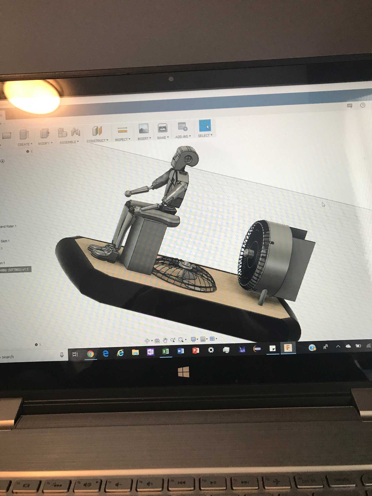
Here’s a picture of the CAD model I’m talking about:

1 Like

Hi @bzalla10!

First of all if the project really requires 32 cores we will find a solution for this like as you mentioned use more efficient meshing.

  1. If you use the MRF approach you are not allowed to use the symmetry as initially intended. So you would have to use the full model and adapt the CAD model by creating a cylinder around the rotating object. Also see: Rotating Zones

  2. & 3. & 4. & 5. \rightarrow See 1 :slight_smile:

Regarding the simplification I would merge faces and give them meaningful names so that when you upload the geometry you already have several faces assigned and can select them with one click.


@vgon_alves, @Get_Barried, @Anware & @jhorv_th , feel free to add additional thoughts here.

Best,

Jousef

Hi @bzalla10,

That is a unique CAD model indeed! So what I would recommend is to first further simplify your CAD model significantly. For example, the representation of the person “piloting” the craft can be simplified to simple round faces with only the most significant features that define the person to be included and all small details otherwise removed.

Next I would recommend even further simplification of the model in general to where only, again, the most prominent and important features are maintained. Do share the project link if you can so we can take a look at the CAD model itself and give further recommendations. Ensure good CAD practices are maintained such as a clean geometry, watertightness of the model, reduction or elimination of sharp edges and odd geometrical shapes, as well as an error free CAD. These steps will allow you to better mesh the model and reduce the computational cost of the mesh significantly if done properly. The reason why simplification of the model is a good starting step is because small features that are present in the CAD and therefore mesh can be computationally expensive to mesh relative to their impact towards the end result, hence, it is important to ensure this step is always done first.

Jousef has adequately answered your question about rotating zones. I still believe the significant work lies within the CAD model and the mesh itself, we can always deal with proper representation of the BCs and further optimization later.

Cheers.

Regards,
Barry

2 Likes

Hi @bzalla10,

I totally agree with Jousef and Barry; the model should be simplified as much as possible. Especially the driver but the fan grill also looks overly detailed.

One thing I’d add: if you need some help with CAD cleaning let me know and I’ll have a look on your model. :slight_smile:

Bests,
Jani

I sent all three of you invites to the project.

1 Like

@bzalla10 @Get_Barried @jhorv_th Just also to add that when you define the MRF, for simplicity, it can include static objects, this will by default make no slip walls ‘spin’ with the MRF however, by assigning it to a rotating wall velocity with 0rad/s this counteracts this, therefore, although static geometry is within the MRF, it will still be static.

Just thought this might help in the mesh creation and simulation stages.

Best,
Darren

So are you saying that I should change the boundary condition on the propeller surfaces from no slip to moving wall velocity?

No, I am saying to avoid complications in the meshing process, you might find that including the grill and surrounds of the propeller into the MRF might be easier, and apply them to a boundary condition that is a 0rad/s rotating wall. This is a technique we tend to use if the rotating geometry is physically close to a non-rotating piece of geometry.

Best,
Darren

1 Like

So I have recently had a string of errors in both the meshing process and the simulation process.

First of all, I used a different person model and simplified it such that the whole model, rider and craft, has 430 faces, I believe. I removed the grills, as I was having too much trouble simplifying the CAD for them, and I don’t think they will affect the total drag coefficient or lift force too much.

For the meshing process, when I try to thicken the skirt (which is just a surface) to be a solid with width of 1 mm, the mesh fails. As this is the only change I made, this must be the cause of the issue; it happened multiple times, and so I reverted back to keeping the skirt as a surface. Other than this, the mesh generally computes pretty well; the best mesh I have with rider, fans, and all contains 94 faces with non-orthogonality greater than 70 degrees. I have tried to fix this by adjusting various meshing parameters, and I got one mesh down to 17 of these same bad faces, I believe. Just for your information, of the 94 bad faces, 2 come from the rider and the rest from the rest of the assembly.

The real issue that is causing much frustration is that 3 times in a row, using the same mesh (the one with the 94 bad faces), the simulation takes 66 minutes to prepare everything (at 0% completion), then stops at 0.0667%, saying just Error where it should say Computing. In the Solver Log, there is no error message; after all the requisite things are set up, the solver computes velocity, displacement (I believe), and pressure; it iterates the pressure solver 54 times then just stops and throws the error. I fixed my rotation zone definition from it previously having incorrect axes, and still the exact same error occurred. I will try to attach a project link so everybody can see for themselves.

If you take a look at the meshing page, the one I used is nRTSWF (no rider thin skirt with fan) mesh - the first one, not nRTSWF 2 or 3. For the Simulation page, the one I’m talking about is hcSimplified.

I made the project public for now, here’s the URL:

1 Like

After a lot of trial and error, I stopped trying to use the rotation zones, as they consistently gave me errors. I thought I had figured out the source of the problem - the solver just couldn’t get the residual for p down below the default absolute tolerance. I adjusted this multiple times, even adjusting it within the solver as well, but that had no effect. I could consider lowering the relaxation factor for p below 0.3 to see if the error was caused by instabilities (again, there was no error message).

Instead, I used the momentum source method. I took the propellers out of the CAD and made what were previously the rotation zones larger, calling them the momentum zones. I created cell zones out of a surface refinement of these volumes in the same way that I had done for the rotation zones. These momentum sources were assigned velocities corresponding to the Q/A of a known fan. I have had success simulating this scenario.

However, I have one question and one (maybe two) problem(s). The question is this - I have cut the craft in half using the z-y plane such that +z is the front, +y is the top, and -x is the simulation region, the z-y plane being a symmetry plane. I know that the drag coefficient is the same regardless of how you cut up the model symmetrically. I also know that if I were looking at the force in the z direction, I would need to multiply my finding by two. Would this still be the case for forces in the y-direction? Again, the +y axis points up through the craft, pointing to the top of the bounding box. I think I should probably multiply it by two, but I wanted to make sure I didn’t report a value two times too large.

My problem is this: the post processor won’t load the solution fields. I realize it takes a while, but I have left my computer alone for hours trying to get the post processor to load, to no avail. I think I know why; my start time is 0, end time 1000, timestep 1, meaning I have 1000 iterations. The write interval is 10 timesteps, meaning there are 100 write intervals. Perhaps all of this data is making the post processor take much too long to load; previously, when the post processor had worked for other simulations, I had just had two frames to deal with - one at 0 seconds, the other at 1000 or 1500 seconds. The obvious solution to this problem would be to lower the amount of iterations, but it doesn’t allow me to. When I try to use 100 iterations and 10 writeouts, it tells me that the write interval is too large. This doesn’t make sense, because the write interval would just be 10 iterations, which is well below the total time of 100 iterations.

If I can get the post-processed results for this simulation and check that they look reasonable, then that will be a big success in this project.

Hi @bzalla10!

I contacted Darren to see if he made further investigations on this. Will also have a quick look at it and tell you what my thoughts on this issue are. Keeping you up-to-date!

Cheers!

Jousef

I just thought of another thing that might be happening to make the results possibly unrealistic. I have downloaded the results and am currently trying to figure out how to post process them in Paraview. When I look at the pressure field for hcSimplePSourcesSquare2 (has both a lift and a thrust momentum source), I see very high pressure inside the skirt, but very little pressure on the bottom of the craft. This has me thinking that perhaps the fluid isn’t flowing through the holes I have in the skirt. If you look in the CAD model, you can see 16 or so holes on the inside of the bottom of the skirt, directing air from the skirt to the underside of the craft to provide the lift. There should be a noticeable pressure difference here from the ambient pressure, but since there’s not, I think that the simulation is not letting any fluid get through the holes.

Does this sound correct or plausible? If so, then would I need to use a Porous Media approach for each hole and make the porosity as high as possible? If not, what do you think could be the reason I’m not seeing a pressure difference? I will post a picture on here soon to show the pressure difference I mean.

Hi @bzalla10,

sounds plausible at first. You could create faces for the inlets and define a velocity inlet for instance but you would need to know which velocity we have at that specific point. On top of that I would assume that your domain is way too small in the spanwise direction and also in front of your vehicle (streamwise direction) which will cause the boundaries to affect your results in a negative way. Additionally I would increase the height between your vehicle and the ground. @vgon_alves & @Get_Barried, feel free to add your two cents here.

Best,

Jousef

Well I need to keep the distance between the craft and the ground as small as it is because that is (one version of) the predicted hover height for the craft parameters. I can vary this hover height to see the effect it has on the drag coefficient and lift forces, but until I get a good solution at this hover height, then I don’t want to change it.

ACTUALLY - I think the no pressure underneath might have been a careless mistake - I believe there actually is significant gauge pressure under the craft, I just was not able to see it due to an odd scaling for the pressure colorbar.

Cool, you might have a way to sort-of loosely validate?/verify? your CFD results by seeing if the pressure integrated over the ground area comes out to the actual weight of the craft… (maybe results of a few sims at different heights could tell you how high it will ride? assuming CofG is good to help it stay level)