I am trying to run a full car sim on an fsae car to analyze the effectiveness of the wings.
When i run the simulation with rolling tires, it is producing unrealistic results.
When i run the simulation without rolling tires, it seems to work alright.
here is the simulation i am running. SimScale
the simulation with the rolling tires is simulation and simulation 2
the simulation without rolling tires is copy of simulation 2.
Any insight would be very appreciated.
-Thank you
Hi @jonesb38!
I think that your boundary conditions mess with your results. Can you try using the “classical” approach by just defining the velocity inlet and pressure outlet? Also you can also use symmetry properties of the model and only simulate the half of the car. Also make sure that the rotating point of the wheels is exactly in the center and has no offset. If there is anything else that seems odd to me I will let you know. @Get_Barried & @Anware, can you see if there is anything else you would modify here?
Best,
Jousef
Hi everyone,
Yes I agree with Jousef. Checking your numerics, you have adjusted it to give the simulation the best chance of converging so the error isn’t there nor in the mesh. What Jousef mentioned is quite spot on where your boundary conditions may be incorrect. What you’ve assigned now makes sense in theory because we are trying to represent the environment as “free air”. However, from my guesses, the way you’ve assigned it will cause the simulation to “force” a solution since your outlet is defined as a velocity outlet. On top of this, having the sides as an inlet-outlet as well will cause some of the numerical solution to exit the domain by the sides due to the turbulence effects present in the simulation and coupled with this “forcing” of the solution, your simulation is bound to hit some sort of continuity error at worse and at best, divergence.
It is clear from your first simulation that that the solution is already unstable and diverging as you can see from not only the convergence plots but also the force plots. In the second simulation with the rotating wheel, the two issues I’ve mentioned earlier are even more prevalent, exacerbated by increased turbulence due to the rotating wheels, hence the very absurd (and diverging) values you have witnessed.
Adjusting the side walls to slip, having a velocity inlet defined while the outlet is a gauge pressure zero outlet will likely resolve your issue. If you have concerns or do see the side walls interacting with the results, then you can increase the size of the bounding box both laterally and vertically to negate these effects. I also recommend increasing the simulation end time to 2000s or more and to check the force plots to see if steady-state convergence is obtained where the final force values do not fluctuate anymore.
Hope this helps.
Cheers.
Regards,
Barry
3 Likes
Thanks for your replies @jousefm, @Get_Barried The reason we have this modeled as a full car is so that we can use the same mesh for simulations that have changing yaw angles for the velocity. We changed the boundary conditions to a more conventional velocity inlet, pressure outlet , and ran the simulation. While the force and moments look more realistic, the post processor, both in simscale and paraview, show no changes in pressure distribution across the body of the car, so it is unclear if any data given from this simulation can be trusted. Would you guys have any insights?
Hi @jonesb38!
If there is no pressure change along the car something is not quite right here. I am a bit busy at the moment so it might take a big until I can investigate the case. Maybe tonight if I cannot sleep  My colleague Barry might jump in before me.
Just asking to be sure: Do you want to have the whole domain also to simulate curve behavior of the vehicle?
Best,
Jousef
@jousefm, yes, we would ideally like to understand the aerodynamic performance of the car in corners, as that is when downforce aids in the angular velocity that the car is capable of. This is our first attempt at aero development, so it’s unlikely we’ll be able to simulate the actual roll of the vehicle as it corners, but adjusting the angle of the air velocity will be enough for what we aim to achieve.
Thanks.
@jonesb38,
this link might help you out: Cornering Flow Case of a racecar on SimScale - #2 by jousefm
You can use the MRF approach and the geometry I have showed you and simply define a velocity inlet and pressure outlet as well as the point of rotation.
Best,
Jousef
Haven’t been able to find a solution to the lack of pressure distribution on the car. Also, I’ve noticed that the car’s contact patches on the tires are not actually contacting the floor plane. Would that have a significant effect on the results?
Thanks
Hi @jonesb38,
Give some time, I will look into post-processing your data offline in ParaView. Get back to you on it in a day or so.
Significant? Debatable. Should it be touching the ground? I would think so as you wouldn’t want a gap there that would affect the performance of the car due to turbulence effects entering the floor and reducing the performance gains from the ground effect.
Maybe @yosukegb4 can better answer your doubts on this.
Cheers.
Regards,
Barry
Hi @jonesb38,
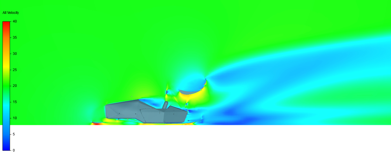
Sorry it took awhile, had a pretty busy week. Shown below are the screenshots for the post-processor (online on SimScale) for the sim “Rotating Tires, Inlet Outlet” > “Run 1”
Y slice Velocity
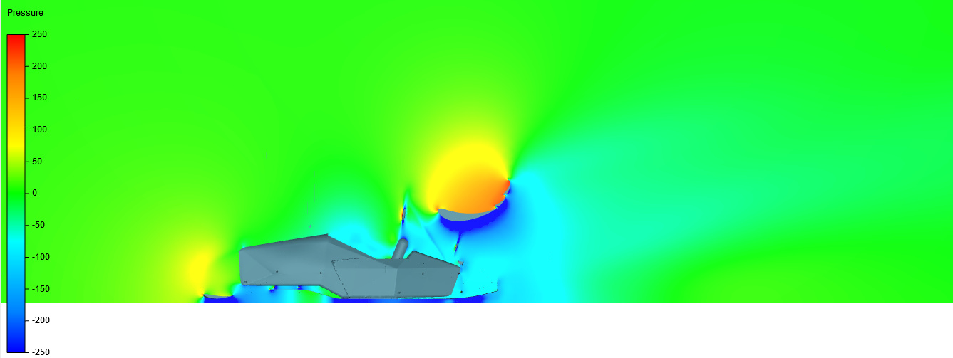
Y slice Pressure
As you can see your values do show up. However, they only will be visible when you adjust the result range. For example the default range on the velocity slice was from 0 to around 1000+ m/s which will effectively give you nothing to visualize . I’ve set it from 0 m/s to 40 m/s to better visualize the velocity gradients as shown in the figures. This is an arbitrary limit and you’ll have to decide on your own what is the preferred upper limit. Pressure, same story.
Note that the post-processor takes awhile to load and depends on your internet connection so do be patient. On top of this you will need to do a 2D slice through the domain to be able to see slices around the area of interest (i.e the geometry). Without doing this, there is no way to visualize flow around your area of interest and you will likely just end up with a solid colour that dosen’t represent anything.
Hope this helps.
Cheers.
Regards,
Barry
2 Likes