Hi @pmparitakis!
Amazing project you are trying to solve here - very interested in the outcome!
The idea would be to create a domain that looks like the one depicted in the picture.
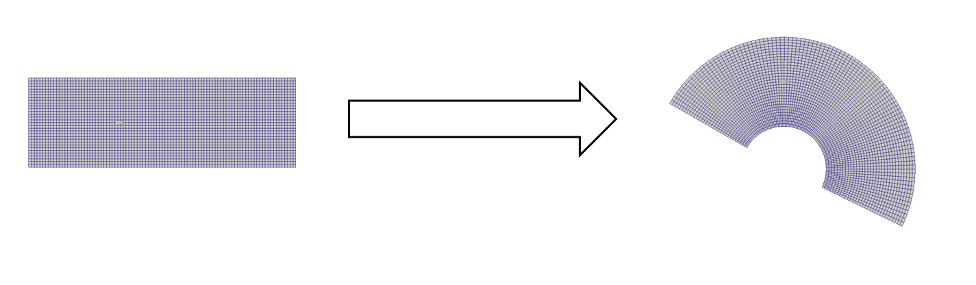
Fig. 1: Straight and curved domain
Another idea would be to have the car in a straight domain but slightly turned by a certain angle (5-20°) to mimic the cornering flow (depends on the track of course). For the boundary conditions you can define the velocity inlet (can also be zero to let the air be driven by the rotating frame) and pressure outlet BC as in other simulations that have been done on racecars and set the other faces to “slip” (except the floor - you could also put “slip” for the wall to avoid boundary layer development but that can be investigated in separate studies). For the MRF part you can set the rotating point to the radius (in your image where the \omega is).
Let me know if the information were helpful and please let us know when you have decided for a domain/finished the CAD model so that we may proceed with the fun part (aka. Simulation & Post-Processing).
Cheers and all the best!
Jousef
Sources:
Fig. 1: Cornering Flow in OpenFOAM® | Experts in CFD | TotalSim Ltd