Hey everyone,
im having more trouble with the convergence of my 7 meter simulations. I have run 4 different wing setup simulaitons and luckily i decided to check on them to find that they are all divergent. I thoroughly checked the sim settings as well as the mesh and didnt find any irregularities. i then used one of the runs (Radius_7_Run_1.3) for testing.
I have so far had divergence on every run so far. Sim run 1 had a mistake and is not considered.
here is the link for sim run 2
I have been slightly modifiying the relaxation factors and non-ortho corrector loops to see if i can achieve convergence but nothing has worked so far. Hopefully someone can help.
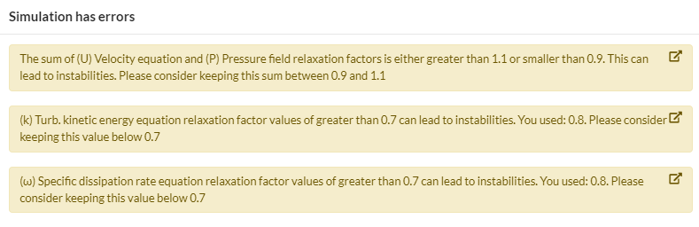
Also, as soon as i try to change the relaxation factors from default settings this “error” shows up. is this more of a warning?
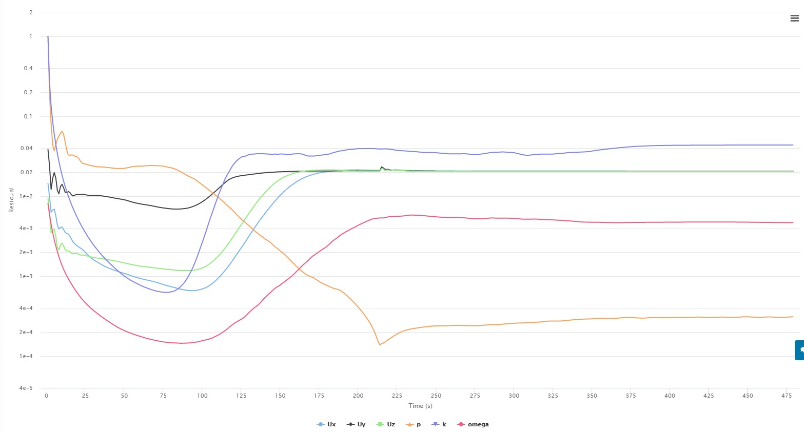
Radius_7_Run_1.3
Sim Run 2
P - 0.3
U - 0.7
K - 0.7
W -0.7
Non-Ortho Loops - 1
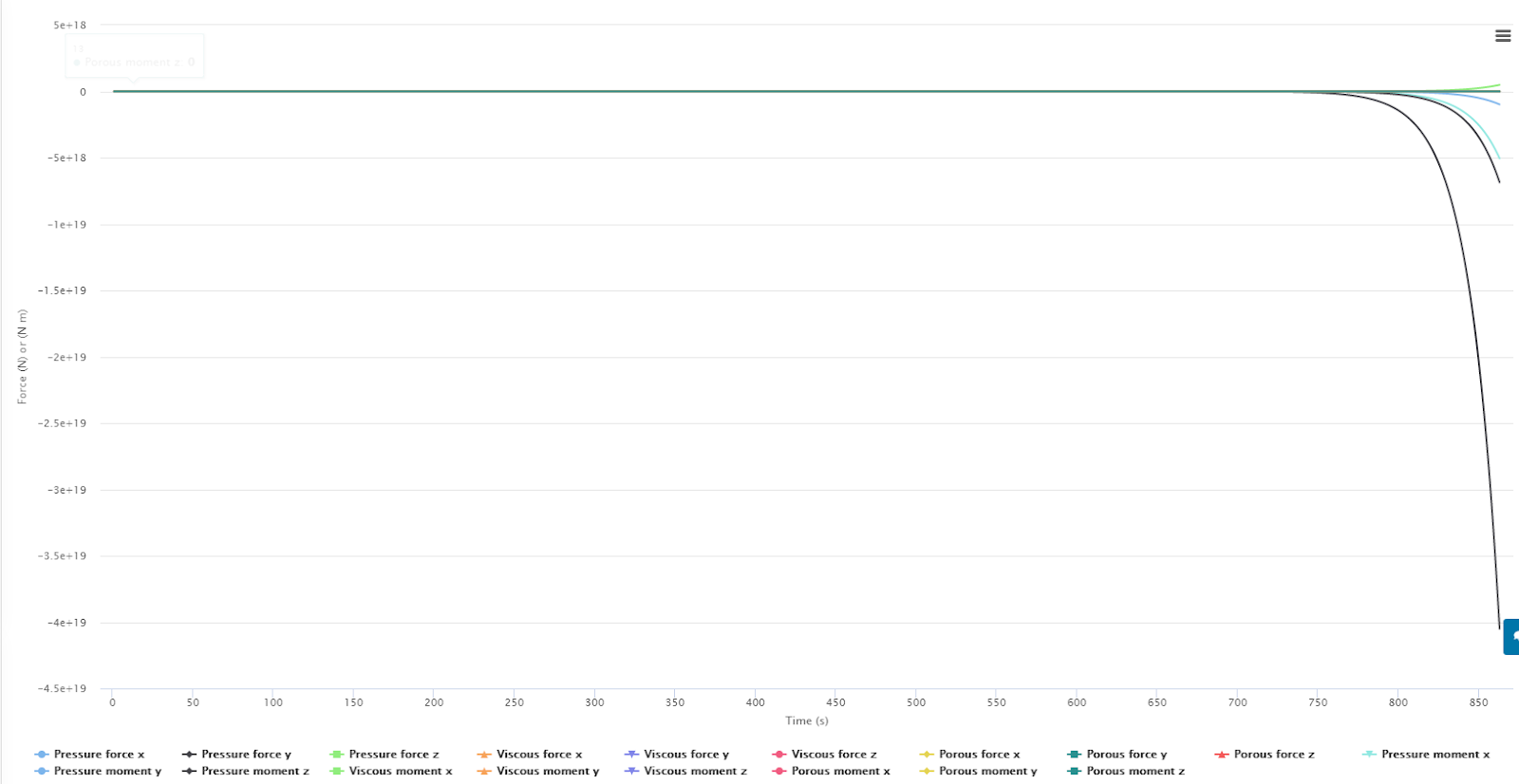
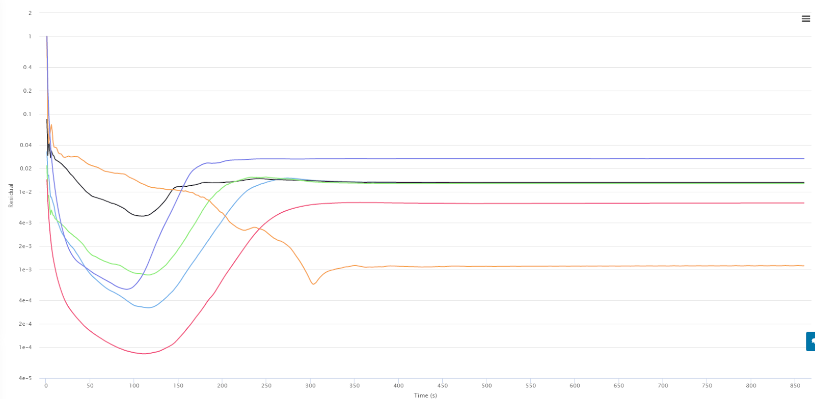
Result - Divergence
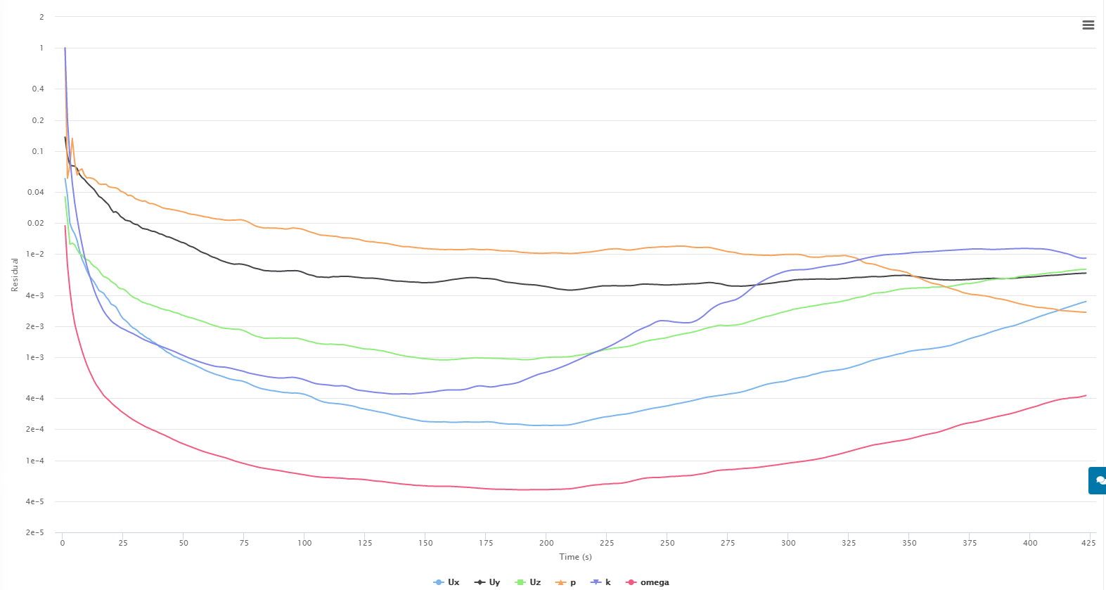
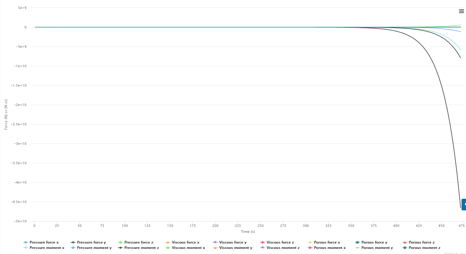
Force Plot
Convergence Plot
Sim Run 3
P - 0.4
U - 0.8
K - 0.8
W -0.8
Non-Ortho Loops - 2
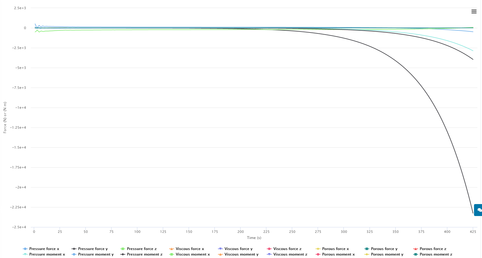
Result - divergence
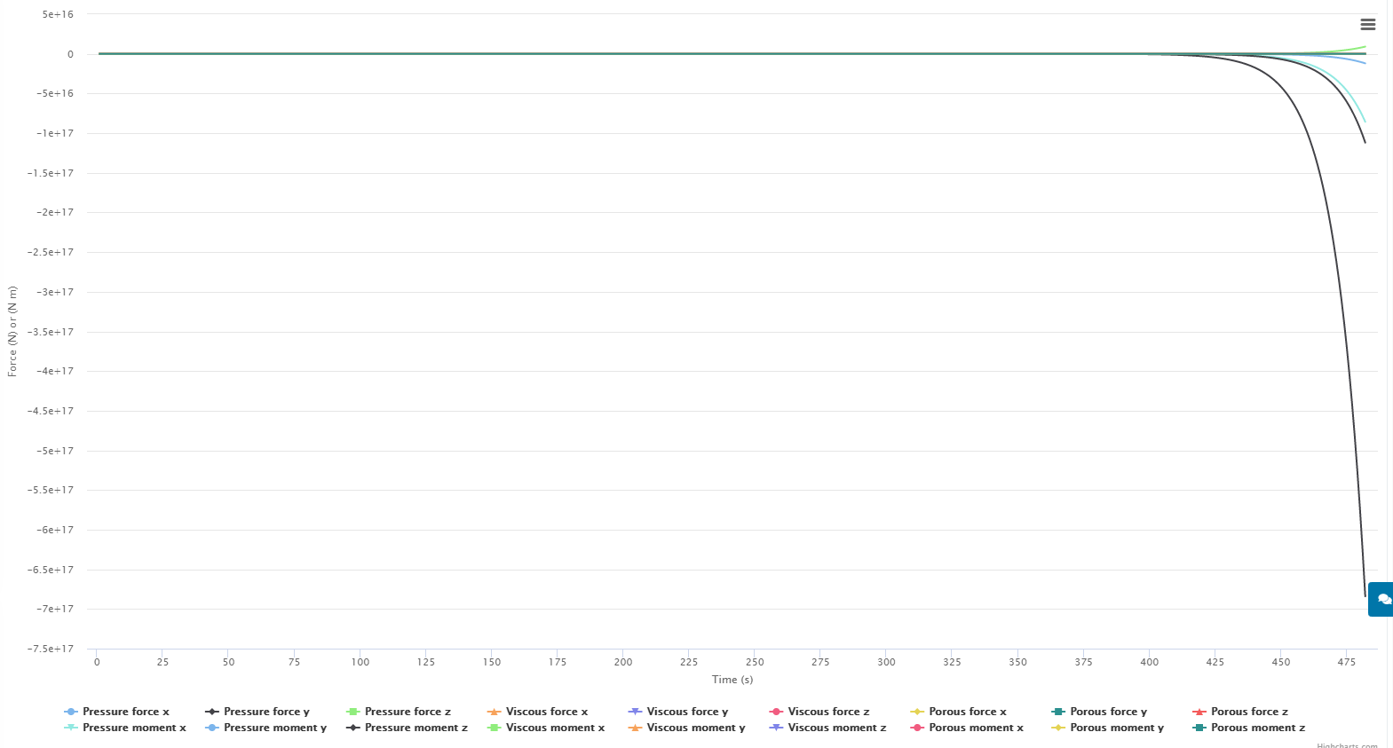
Force Plot
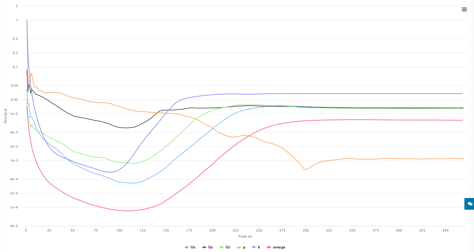
Convergence Plot
Sim Run 4
P - 0.3
U - 0.7
K - 0.7
W -0.7
Non-Ortho Loops - 2
Result - divergence
Force Plot
Convergence Plot
For the next run i am trying tighter relaxation factors, because after reading this A post from this thread: Most Popular Errors of Simulation - #3 by jprobst Johannes is saying that LOWERING the values of p,u,k, and w will help with convergence. I had thought that values closer to 1 help with convergence through the description from OPENfoam
Could my simulation be diverging this time because it is too loose? As in, the default values are already accepting too much of the new iteration results making each successive calculation have larger and larger residuals?
Sim Run 5
P - 0.2
U - 0.5
K - 0.5
W -0.5
Non-Ortho Loops - 2
Result - diverged
Force Plot
Convergence plot
Dan