Relax Factors Issue

I agree, and until we get some answers to my questions of Post 1 and beyond, I believe that the only safe thing we can do here is to never change Relax Factors from the DEFAULT values.

With the data we have assembled about changing Relax Factors, I can see no way to justify changing them.

Even using DEFAULTs, I am very wary of the reliability of result predictions in any of my CFD simulations…

1 Like

Hi All,

My experience with relaxation factors comes from requiring the simulation to converge sufficiently in exchange for simulation time.

Sometimes a complex mesh or meshes for highly complex phenomena is very difficult to refine and even after significant iterations of mesh refinement, there will still be cells that will cause significant numerical fluctuations in the residuals. That’s where the relaxation factors come in. With relaxation factors you are able to influence either the final convergence or speed of the convergence. In exchange, you sacrifice either simulation time (under-relaxation) or convergence stability (over-relaxation).

So all in all, it really depends on what you need. Say if your simulation is very complex, difficult to refine but you have the computing time and resources available, usage of under-relaxation factors to allow the simulation to converge might be what is just needed to get the results you want.

Similarly, if you have a relatively simple case with a good mesh that is taking significantly longer to converge, you can apply over-relaxation to allow it to converge faster provided the instability in residuals does not cause the solver to prompt and error.

In use cases, as Ric has pointed out, one would leave the relaxation factors as default and then apply them as needed. Relaxation factors should not affect the result, merely the convergence. Of course then, a poor convergence will mean inaccurate results so keep that in mind.

As for the math, I went to do some searching and this simple equation poped out from the CFD forums.

Under and over relaxation factors control the stability and convergence rate of the iterative process.The under relaxation factor increases the stability while over relaxation increases the rate of convergence.

xk+1 = w.xcal + (1-w).xk
yk+1 = w.ycal + (1-w).yk

For 0<w<1, the method is known as successive under relaxation.
For 1<w<2, the method is known as successive over relaxation.

where xcal is the value calculated based on xk

If anyone can find a proper mathematical description and break it down that would be great.

Cheers.

1 Like

Barry, thanks for your research and insight, but it seems to magnify my concerns.

With our data, we have shown that the accepted rules do not seem to apply at the same time here.

Unfortunately, I do not think the issue will get resolved to my satisfaction until someone actually reviews our data and our sim runs to show us where we have gone wrong.

It seems that we can pick any relax factors and get results to be of any value we want while justifying doing so by citing things like ‘we needed to get the residuals to a lower level’, or’ it was taking too long to converge’.

Relax factor adjustments just seem like a convenient way to validate CFD results to experimental data to me…

And I see no reason to have faith that the default values actually give us the most accurate results.

I will try to present our results in a way that their randomness can be more clearly seen (if that is even possible)

Does anyone have any ideas on how to show the issue using our data in a more clear manner?

I think it may be time that I move this ‘Relax factors’ topic back to the public forum so that we might get more input on this pervasive issue.

I see that while I was gone, that SimScale has decided to give us an ‘Auto Relax’ feature and also to make it the default.

I am totally mystified as to why this was done when relax factors are such a problem since they affect the results to such a large degree and that there is a very serious contradiction in basic theories as to what levels they should be set to.

Can we at least have a full explanation as to what values are used when ‘Auto Relax’ is used :question:

Dale,

I am too struggling with some of these parameters, with much less knowledge then you or most of the other users on the forum. Currently, when manual is selected, these are the default settings.

image

And these are the settings for Automatic
image

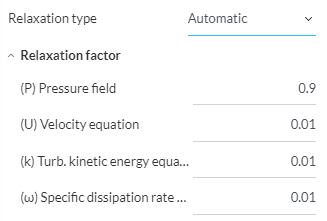
The automatic factors seem quite low (except for pressure) but i think someone on the forum told me that the automatic factors start out much higher, and are then tightened towards the end of the simulations. I just cant remember where that was said.

HOWEVER,

When doing some research on Non-Orthogonality, i did a small and basic thread here, with how mesh settings effects Non-orthogonal cell count.

For the simulation side, I found that using Non-Orthogonal corrector loops is necessary when there are higher numbers of Non-orthogonal cells, and when these cells have a higher angle (above 70 deg) Im not sure how strong the connection is between the corrector loops and relaxation factors, but my assumption is that both are necessary for convergence, especially with meshes of higher numbers of illegal cells.

Basically, as i understand it, most CFD solvers use the Over-relaxation method developed by Hrvoje Jasak, where the treatment of the explicit term during discretization allows for less corrector loops to achieve convergence. This is best said from his thesis:

Source:
Google Search
(Error Analysis and Estimation for the Finite Volume Method with Applications to Fluid Flows by: Hrvoje Jasak)

PG 113

In this study, the diffusion term will therefore be split into the implicit orthogonal contribution, which includes only the first neighbours of the cell and creates a diagonally equal matrix and the non orthogonal correction, which will be added to the source. If it is important to resolve the non-orthogonal parts of the diffusion operators (like in the case of the pressure equation, see Section 3.8), non-orthogonal correctors are included. The system of algebraic equations, Eqn. (3.42), will be solved several times. Each new solution will be used to update the non-orthogonal correction terms, until the desired tolerance is met. It should again be noted that this practice only improves the quality of the matrix but does not guarantee boundedness. If boundedness is essential, the non-orthogonal contribution should be discarded, thus creating a discretisation error described in Section 3.6.

Jasak is saying that if boundness (convergence) cannot be achieved, that the explicit term should be discarded. He then continues to say:

PG 114

The above discussion concentrates on the analysis of the discretisation on a term by-term basis. In reality, all of the above coefficients contribute to the matrix, thus influencing the properties of the system. It has been shown that the only terms that actually enhance the diagonal dominance are the linear part of the source and the temporal derivative. In steady-state calculations, the beneficial influence of the temporal derivative on the diagonal dominance does not exist. In order to enable the use iterative solvers, the diagonal dominance needs to be enhanced in some other way, namely through under-relaxation.

Then some confusing equations … followed by

PG 115

Here, (theta p) here represents the value of (theta)’ from the previous iteration and a is the under-relaxation factor (0 < a ^ 1).

And finally the relaxation factor definition from OpenFOAM

Source: OpenFoam

Under-relaxation works by limiting the amount which a variable changes from one iteration to the next, either by modifying the solution matrix and source prior to solving for a field or by modifying the field directly. An under-relaxation factor α, 0 < α ≤ 1 elax pecial {t4ht= specifies the amount of under-relaxation, ranging from none at all for α = 1 elax pecial {t4ht= and increasing in strength as α → 0 elax pecial {t4ht=. The limiting case where α = 0 elax pecial {t4ht= represents a solution which does not change at all with successive iterations. An optimum choice of α elax pecial {t4ht= is one that is small enough to ensure stable computation but large enough to move the iterative process forward quickly; values of α elax pecial {t4ht= as high as 0.9 can ensure stability in some cases and anything much below, say, 0.2 are prohibitively restrictive in slowing the iterative process.

So as i understand it. Non-orthogonal corrector loops help to achieve accuracy. When the non-orthogonal component (explicit term) is too large, it must be discarded, leaving only the orthogonal contribution (implicit term). This leads to necessity of under relaxation factors to make up for the deletion of this non-orthogonal component in order to either get an accurate reading (lower relaxation factor values eg: 0.2, 05) or to allow the inaccuracies to slide, in favor of convergence and speed.

I am taking this assumption from the only source i have read on this topic, the thesis from Jasak. Please correct me, as i am only attempting to understand what is going on here and apply it to my simulations.

Working off of this information, I am currently getting some very incorrect numbers on my full car sims as shown below. Not to try and change the topic of discussion but i have changed both of these settings in hopes that they would help.

First run here shows the following coefficient graph that is very wrong.

Relaxation type: Automatic
Relaxation factors:
P = 0.3
U = 0.7
K = 0.7
W = 0.7
Non- orthogonal correction = 0
EDIT
Sim time = 21.76 hrs
Core hours = 695.5

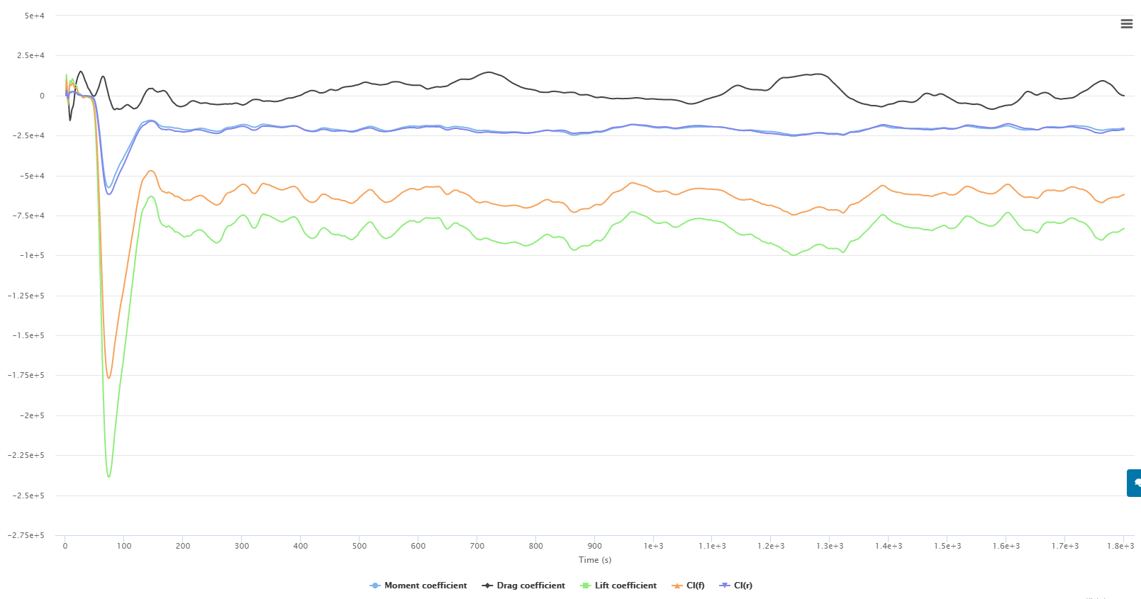
Second run: here reduced relaxation factors and added a non-orthogonal correction loop.
Relaxation type: Automatic
Relaxation factors:
P = 0.3
U = 0.7
K = 0.5
W = 0.5
Non- orthogonal correction = 1
EDIT
Sim time = 23.23 hrs
Core hours = 743.5

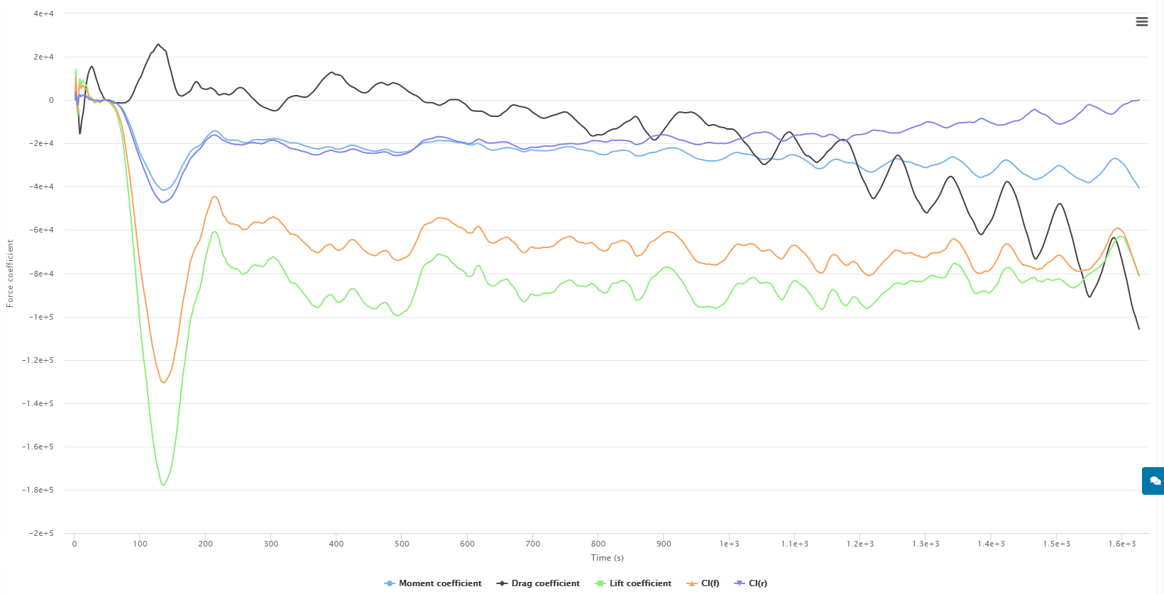
This brings me to the mesh quality as the most likely cause - here

Most of my previous simulations done with Simscale have had a illegal cell count of around 2-500 with a 15-20 million total cell count. Most of the illegal cells are Non-orthogonal. These previous simulations also had the max non-orthogonal quality setting at 75 deg. When changing this value to 70 deg, the amount of non-orthogonal cells jumps to 5000 on current meshes.

Question: does the amount of illegal cells (in this case non- orthogonal cells) that are recorded after the mesh is created, affect the simulation? As in, do the solvers treat the discretisation of these cells differently based on how many are reported as illegal, or do the solvers treat based on the actual degree of non-orthogonality

Sorry for the long post, i have a bad habit of doing that haha

Dan

Hey @dschroeder & @DaleKramer!

I already forwarded this and there will be some progress related to the relaxation factor! Tagging my colleague @sguenther here in any case.

Best,

Jousef

Hi Dan,

Glad to see you jump in here with an amazing amount of research! :smiley:

As I have time I will respond in detail where I can but it looks like a look of what you have come up with is over my head right now and I will have to research and experiment more when I get some time and more core hours…

Dale

Dale,

Im sure we both agree that some help on this topic would be useful. I would also like to do tests with smaller geometries but i dont have time right now as i urgently need to get results for my thesis. As of now, very few meshes are working due to the 3 adjacent cell problem. With the only mesh that did succeeded, i made 2 simulations with terrible results in the links i shared above.

I am not sure how the mesh quality is related to simulation convergence in terms of reported illegal cells, but i am getting really frustrated and wasting a lot of core hours on this problem.

I am now doing another test where the max non-orthogonality will be reverted back to 75, which will drastically lower the illegal cell count. Then, if by some miracle, the mesh succeeds, i will do 2 more simulations with the same settings as before, in an attempt to see the difference. I just hope that the new mesh wont have the convergence problems that the previous runs had.

Ill post anything i find, but i could use some help!

Dan

Wow, about 15,000 mesh faces in the vehicles geometry …

I see you are only layering the wings and endplates and a BMB face…

Have you used our method of getting 11 or more mesh quality parameters by installing OF and looking at them in ParaView?

I too would be concerned with such a high ratio of illegal cells. (5000 in a 20,000,000 cell mesh)

I am not using AutoRelax at all right now. I use .3p.7u.3kw

I have not played much with orthogonal correctors but it looks like they are in order for you.

Have you got simpler geometries that give results that are not unreal (I can’t find any of your forces results that are not unreal), if so what changes caused the issues?

I will look further…

Dale,

I have not checked the mesh quality parameters as do not have OF installed. I have never used the native OF but i am aware that it can check the mesh quality.

I can easily lower the illegal cell count by changing the max non-ortho Quality setting to 75 deg, but im still not sure if that has the desired effect.

My simulation setups and methodology is as follows:

  1. I performed all my Non-ortho reduction testing on the wheels as they had a significant amount due to the geometry. This is found in my thread here

  2. I used my research and new strategies to create a successful 1/2 car mesh to validate the results. This project is here

The half car simulation was done with max non-ortho quality of 70 deg, which resluted in the following illegal cell count.

Checking faces in error :
non-orthogonality > 70 degrees : 2682
faces with face pyramid volume < 1e-13 : 15
faces with concavity > 80 degrees : 1
faces with skewness > 4 (internal) or 20 (boundary) : 4
faces with interpolation weights (0…1) < 0.02 : 0
faces with volume ratio of neighbour cells < 0.01 : 3
faces with face twist < 0.01 : 15
faces on cells with determinant < 0.001 : 0

This project was also the original testing ground for my radiator fan / rad fan MRF zone testing. Since this was successful, my plan was to simply make a full car sim because i naively though that this would work no problem

And the stable results with default settings for relaxation factors, with one non-ortho corrector loop

image

Force plot

Coefficients Plot

These results made me think that all was well and good … NOPE.

After the first attempts at a full car simulation (with yaw, pitch, roll, and steering angle) i knew this would be a battle. I immediately had mesh failures, due to memory problems.

  • I reduced the region refinement settings which fixed this

Once the mesh began to work it failed again due to the 3 adjacent faces problem.

  • with support from the Simscale staff i was able to get the locations of these points on the geometry and fix it.

Then i finally get a 20 million cell mesh to work, with rotating fan assembly and all… Simulation ran out of memory.

This led me to delete the fan assembly to gain some cells back as a buffer. Since i changed this geometry, the 3 adjacent cell problem came back.

  • again receive quick support from Simscale staff … geometry fixed … good mesh.

Simulate results - wildly wrong results as you saw in the links from my first post.

Now i am still confused because my half car sim with half the illegal cells (2682) worked just fine, so i dont think thats the problem … but i have no idea.

So to conclude. I have a more complicated mesh working with converged results that also has a large number of Non-ortho cells.

Dan

Hey everyone,

I wanted to add some updates to this topic. First of all i had success with the simulations in my first post. I found that i missed a decimal place on one of the rotating wheel conditions that sent it 6000 meters away and not 0.6 meters haha.

Anyways, I have since received results from 3 simulations that i wanted to share.

First is the results from my first sim that was failing - Radius_19_Run_1.1_Sim_3
Second are the results from two sims of the SAME MESH with the only difference being the number of Non-Orthogonal Corrector Loops. - Radius_19_Run_2.3_Sim_1 & 2
Run 1.1 _ Sim 3

Run 2.3 _ Sim 1

Run 2.3 _ Sim 2

Two things to notice in this table.

  1. The simulation Run 1.1 had a max non-orthogonal setting of 70 resulting in 5045 illegal Non-ortho cells in the mesh. The mesh for Run 2.3 was set to 75 deg, resulting in only 82 illegal cells. This however did not drastically effect the results.

They are different geometries (wing AoA was changed) so i expected different values, but they are not way off. Somewhat of a indication to the question of how illegal cells effect the simulation.

  1. Between Simulation run 1 & 2 of the Run 2.3, the only change was the number of Non-Ortho correctors, changed from 1 loop in the first sim to 0 in the second sim. These results however show a difference which leads me to believe that one run could be oscillating around a more correct solution.

These results are by no means thorough enough to make a definitive answer. However i feel that they are leading somewhere. More evidence is shown in the following plots where i isolated the Y moment results as they were the most unstable.

For this run the last iteration, where the sim was canceled had the best results

Radius_19_run_2.3_Sim_1 Full car - Y moment at CoG
Iteration of interest 1455
Y moment = -35.97
Number of Non-Orthogonal Corrector Loops = 1


.
.
.
Then in the second simulation with 0 corrector loops, I recorded the data the same iteration from Simulation 1

Radius_19_run_2.3_Sim_2 Full car - Y moment at CoG
Iteration of interest = 1455
Y moment = -30.01

And at the best ORSI value of the whole run

ORSI lowset % difference for run
Iteration of interest = 1383
Y moment = 29.37
Number of Non-Orthogonal Corrector Loops = 0

This shows a difference of 6 Newtons, which is not a lot, but my whole data set for the Aero Map is dependent on these small differences in pitching moment.

One definite result is that using Non-Orthogonal corrector loops means the simulation will take longer (not unexpected). However this makes me think of what @Get_Barried said earlier just switching relaxation factors with the application of Non-Ortho Correctors.

Is the Non-Orthogonal Corrector loop really giving more accurate results (in my situation) or is it simply another tool that allows for stability faster?

As previously stated, there are many problems with my data given here,

  • I only did 3 tests
  • I could be using incorrect ORSI data points for comparison
  • The unlimited amount of inaccuracies in my mesh/Simulation/analysis
  • Simulations are not run long enough to see true convergence

Anyways, anyone have any ideas on where to go from here, I cannot go too in depth with this as i have to get results soon, however it would be nice to know the error percentage when using incorrect numerical settings. Might be a rabbit hole, but Dale already knows I love those haha

Dan

2 Likes

I see you seem to be interested in Pressure Moment Y. I did not let the ORSI program analyze moments since I could never make sense of their results (just last week I had the need to get ORSI on Pressure Moment Y so I made a simple code change to show it), perhaps I should get you a compiled version that lets you ORSI all 3 moments.

So, I ran ORSI 500i500ma on your Run 2.3_Sim1 (CoG faces), here it is:

Still near 10% ORSI so maybe longer runs needed ???

Let me know if you want that special code version to show the 3 moments… :wink: (6 more if you want viscous too)

This is the point of this whole topic…

Relax factors seem to be a crutch to get the “results you want”, whether that is, to get results that make sense to you or to match experimental values…

In my mind it is just plain wrong to do that… we need to set relax factors that make sense by theory, not to get results we want…

Auto Relax throws another monkey wrench into the mix :cry:

If we got the same results with any Relax Factors that converge, I would not be so upset…

Dale,

thanks so much for checking the Moment data for me! I was also looking for this in your ORSI program but its great that you could add this so easily. I agree that i could run all of these sims longer, and the one running now is going until 1800 iterations. The problem is that i have quite a few to do and i dont want to use up that many core hours. I could however use the Y moment feature in the ORSI program. That would help verify the last important parameter for the front/rear downforce calculation.

However, this is why i put my results in this thread. If i can use the relaxation factors to speed up convergence then i wont have to run my sims so long. Is this actually true though?

I agree this question should be investigated, because the way i understand it as of now, higher values of under relaxation (0.5-0.1) allows the simulation to converge quickly but obtains results at a larger deviance from the “true” value. Like you said, results you want. Maybe not accurate but results nonetheless. Im thinking this would be good to use on bad meshes or on simulations where the results can be 5% off of the correct value.

Low values of under relaxation (0-0.5) are used to really hone in on the exact values that can be used to compare with experimental findings, maybe 1% or lower tolerance.

I basically see the relaxation factors as a Speed of results vs accuracy of results. This is not really that much different then any other factor that follows these same principles.

Good CAD accuracy to real life model = accurate results with long simulation time
OK CAD accuracy to real life model = ok results with shorter simulation time

Highly refined mesh to capture all surfaces perfectly = accurate results with long simulation time
Somewhat coarse mesh due to computational restrictions = ok results with shorter simulation time

I also agree that the auto relax needs to be explained to make me want to use it. The other automated settings i stay away from so that i can have control over the process.

Dan

Hi Both,

The balance I am implying here is less to do with accuracy of the results and more to do with practicality. Doing CFD in a practical sense is always about this balance and thats where I’m approaching it from. If I sacrifice some result accuracy but get a result in 1/3 of the expected run time, thats an approach that I will likely take.

Of course the other end of the spectrum is also depending on how sensitive your results are. If say the result of a 1% to 2% difference adversely affects your problem, then you have to exchange time for accuracy instead.

All in all, this doesnt mean that the investigation into how the relax factors affect results should stop, instead I think the work both of you are doing is fantastic and do keep on going. Its been very insightful to read through the data and form some conclusions and assumptions.

Cheers.

Regards,
Barry

Hi Barry!

In the data that Ric and I presented in the first couple posts here and for the types of aerodynamic simulations we were investigating, relax factors varied the Drag results significantly from -7% to +50% away from experimental results and made verification of experimental results impossible.

I have not seen verification’s that are not affected by this problem and have not seen any note in verification’s that suggest CFD inaccuracies are this great in the Drag magnitudes.

There is no ‘best practice’ that I can see for Relax factors as we have with other CFD setup items.

That much Drag variation is not acceptable for my needs so I am stuck with little hope for accurate CFD analysis (but I still love and will use CFD with these inaccuracies kept in mind).

Hi Dale,

Agreed. Drag has always always been an issue even in my studies.

Side question, for the studies you and @Ricardopg conducted, I assumed you both did 2D studies, using k-w SST and full resolution wall functions with y+ <1 at 99% layering achieved?

Yes but not 2D, we are able to use a very short span airfoil section and slip walls at the ends of the sections which produced very good flow at the BMB walls.

Here is a view of one of my meshes at the BMB wall:

Hey Ric (@Ricardopg), any way you can make the links work again for the results you presented?

I tried to open the links, the runs are gone, apparently

I had 10~ projects with very similar names, all containing NACA tests. To save space, I ended up deleting most of the projects with a small number of simulations :man_facepalming: