I’m doing a CFD simulation to see the flow around a full sized scale model of a person and bike. No matter how much I refine the surface of my mesh, I continue to get y+ values near 800, and i need to get it down to between 30-100 as I’m using no-slip wall functions. Can someone inform me on what I may be doing wrong?
current set up:
Hex-dominant parametrix
Bounding box resolution: (20, 5, 10)
Surface Refinement: min, max (10, 10)
Feature Refinement: level 9, distance 0.005m, include angle 100deg
inflate boundary layer: layers 1, expansion ratio 1.2, min 1e-7, final layer 1e-4
the region refinement is split into three, with the other being level 0, then level 2, then closest to the bike level 3
For this project, I recommend that you use the standard meshing tool, as this geometry is quite complex, You’d have to extract the flow region, either by a boolean operation in your CAD software or via an enclosure operation in SimScale. You also have 2 sheet bodies in one of the hands of the cyclist, which could potentially be causing you issues right now.
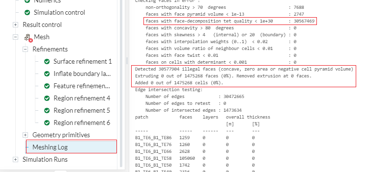
Just not to leave you hanging in respect to y+, this is the (or one of the) causes for your issues with layers: all of them are being deleted, as you can see in the meshing log:
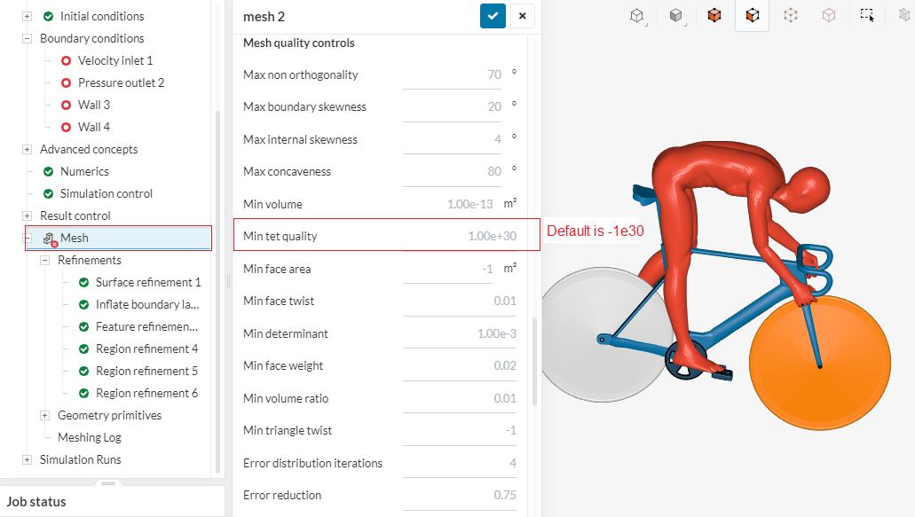
This quality parameter (min tet quality) can be turned OFF by inputting a big negative number (e.g. -1e30, which is the default setting). I believe you must have changed it by mistake to 1e30:
Thank you very much, I’ve uploaded a version of the model that one solid now to get rid of the sheet, although it won’t let me put an enclosure around it or select the standard mesh option. Are these only options if there are multiple solids?
Standard mesh (I think) was originally designed for internal flow, so think about your problem as an internal flow one where the inside of the “pipe” is actually your enclosure volume. This is easy to achieve in most solid modeling programs - simply make a big box around your little guy and then do a boolean subtract of the little guy from the big box.
I’d also recommend that you cut the whole thing in half and apply the symmetry boundary condition to split wall. This will cut your simulation and meshing times in half.
I’ve done the boolean thing, although i’m unaccustomed with the standard algorithm, an error has appeared because it is a multi-region mesh, although i dont know what to assign.
Your “Design0enclosure” geometry is not a boolean’d solid… it’s a bunch of separate solids. I suggest you upload as STEP and make sure all you see is faces. If that doesn’t make sense, revisit the Ahmed body study project I posted for a great example. Take your enclosure volume and boolean subtract the guy, bike, etc from that. The resulting solid with a bike-guy shaped bubble in the middle is what you upload.
On a separate note, that is some extremely complex geometry. I’d suggest you think about how it might be simplified. Maybe remove axles, simplify cranks, pedals, does the guy really need six pack abs? Dos he need to have fingers? etc. For every tiny bit of geometry you will need to have cells that are several times smaller to define it. The mesh for this thing is inevitably going to be huge, but as you’ve modeled I can almost guarantee you won’t be able to get a mesh done within the limits of the “free plan”.