Dear community,
I hope you are doing well.
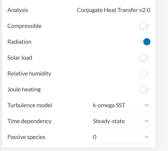
I am having some problems with my Final Engineering Project: I am trying to simulate the heat loss from a cattle trough to the environment in order to understand the freezing mechanism and provide a solution to this problem.
My simulation consists of a 2D domain to reduce simulation time, where I have two flow regions. The first one, which looks like half of a circle, represents the water in the trough, the material I have assigned to it is a solid with water properties to avoid natural convection. The other flow region represents part of the environment surrounding the trough and I attribute the properties of air to it. However, to minimize the effects of convection in the air I change the specific heat to 1.
The assigned boundary conditions are described in the following image:
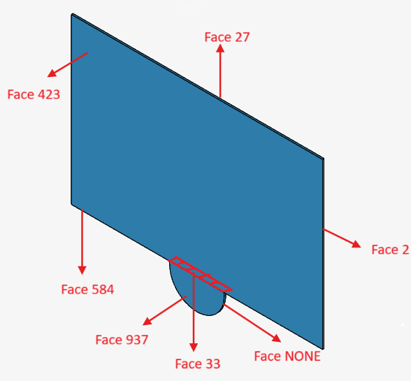
Face 423: Slip, Adiabatic, Opaque (Emissivity = 0)
FAce 937: No Slip (solid), Adiabatic, Opaque (Emissivity = 0)
Faces 2, 548, 27: Slip, Fixed temperature=-10°C, Opaque (Emissivity =1)
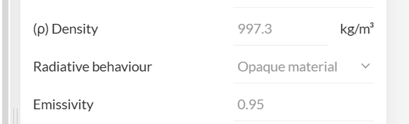
Face NONE: No slip, Fixed Heat Flux = 10W/m^2), Opaque (Emissivity= 0,95 (water))
Note that Face 33 has not been asigned any boundary condition because it is an interface.
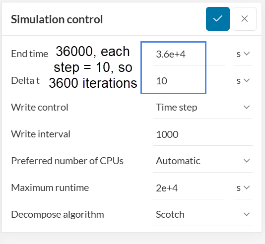
I ran the simulation for 86.400 seconds (24 hours).
The problem appears when I obtain the area integral of the faces bordering the environment: unexpectedly the faces parallel to the interface face are the ones that exchange the most radiative heat (Qr). Naturally, the face opposite to the interface should be the one receiving the most radiative heat and that puzzles me a lot.
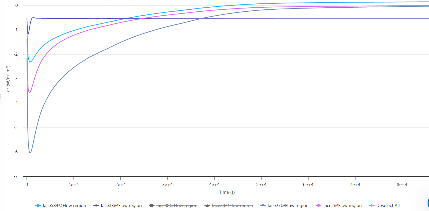
The energy balance between the two flow regions is correct, since the amount of heat introduced by Face NONE is the same that enters in Face 33. However, inside the air flow region the distribution is not phically correct as I mentioned before.
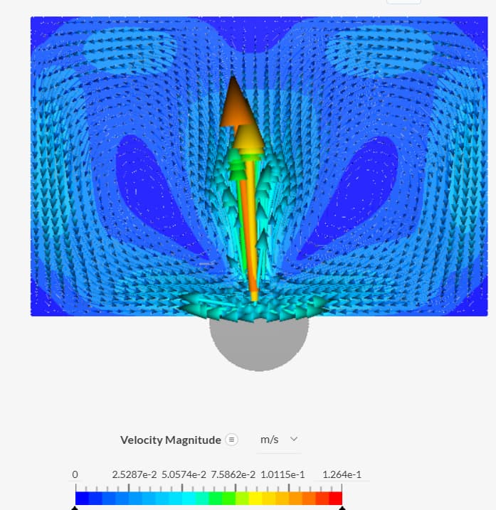
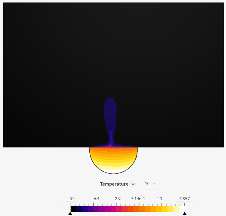
I will also post some images of the solution fields to help you understand the whole scenario.
I hope you can help me,
Best regards,
Dante.