@sholz, LOL, this topic may get much longer with me having a bone in my mouth now…
Just to make it easier, for those that follow, to quickly see what solution best served you for your Post #1 issues, can you mark any single one of the posts that give the answer which you like best, as the ‘answer’ (there should be a checkbox for ‘Mark post as answer’ or something like that for each post here, but you can only select one post in this topic as the answer to this whole topic )
EDIT: You can also add an EDIT: comment to the end of your 1st post to summarize the journey to that answer…
I will be reporting some neat things I am working on here which may or may not help you further on your project
.
.
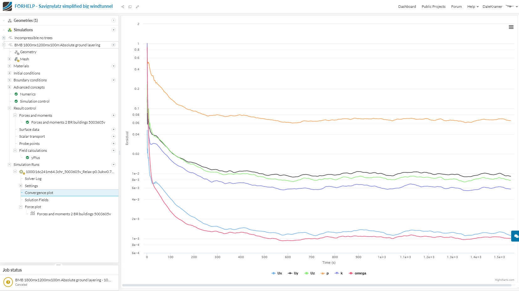
. EDIT: At this point, I have decided to use a mesh which I made and this simulation run using my mesh, to use as a basic starting point for my further analysis… I will explain more about the sim run details as I continue from here…
The BMB size of my mesh is 1800m X 1200m X 100m, the city geometry extent is about 800m X 800m X 25m
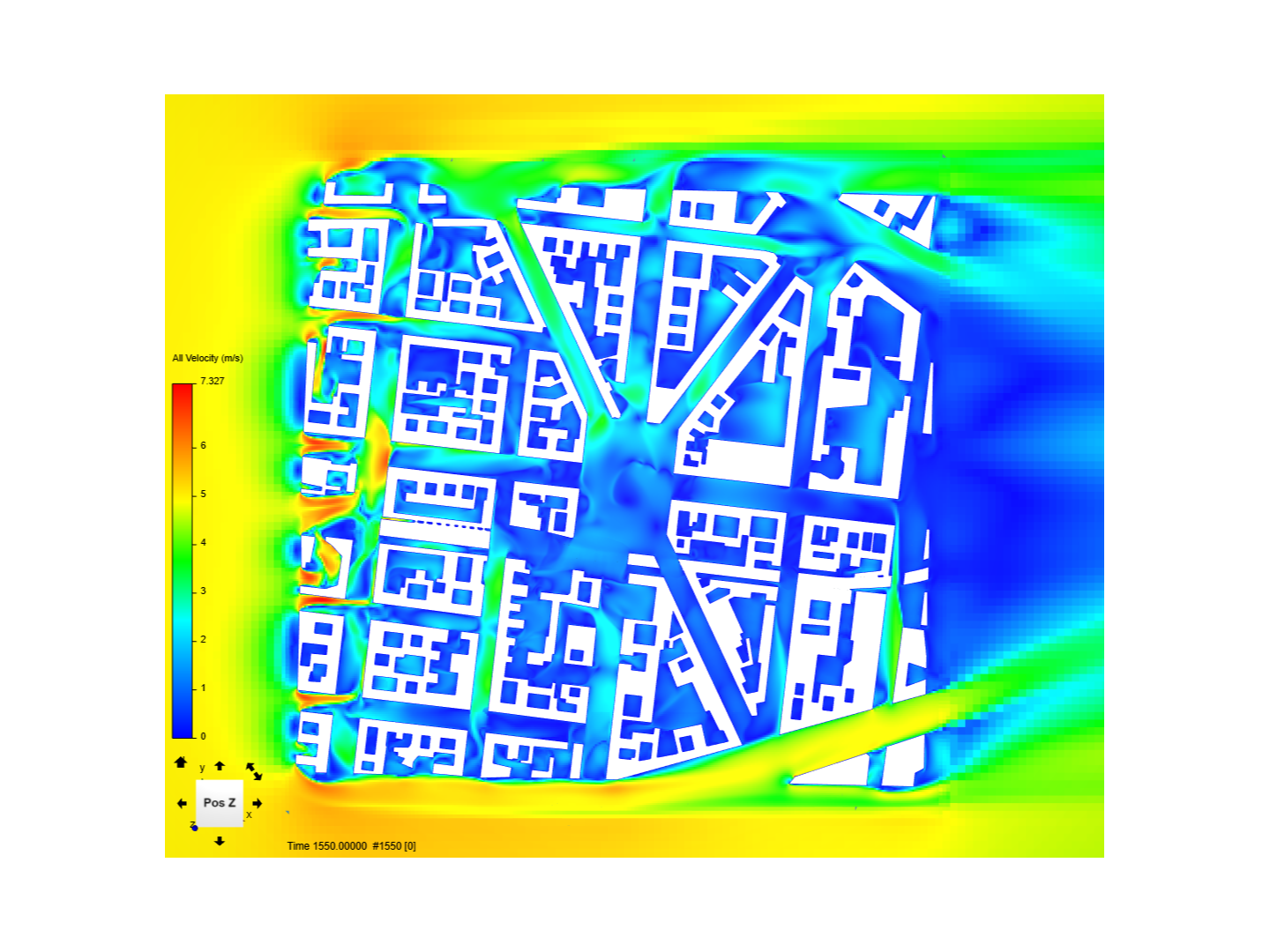
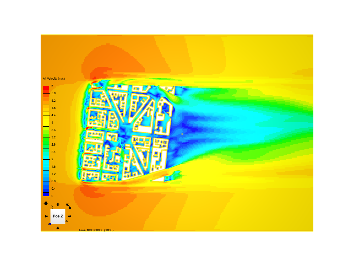
Here is the All Velocity plot inside the city at 2 meters above the ground, Max Velocity in the whole domain at 2m seems to be 7.327 mps (5mps inlets velocity):
Thanks again for you support!
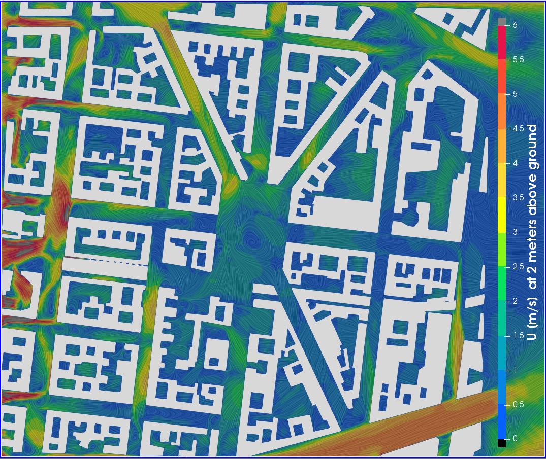
I tested both approuches, 1. BC slip wall and 2. BC Zero Gradient. Both times I activated Potential Foam Initialization. Also, I deleted the cut blocks an west side of the geometrie, so wind hit complete block structures and is not artifically swirled, creating a non realistic higher wind speed on the north-south street axis (first one on left hand side).
Here the results:
On the first glance, both results seem to be very simular. However, closer examination shows there are differences, for eample: main street in east west direction
BC zero gradient: shows higher wind speed within street section before square and lower windspeed on the second half.
BC slip walls: more or less same wind speed before and after square.
From my experiance of the place, constant wind speed within street section before and after square are more likely. However, on site measurement would be needed to confirm this assumption.