Dear Simscale Team,
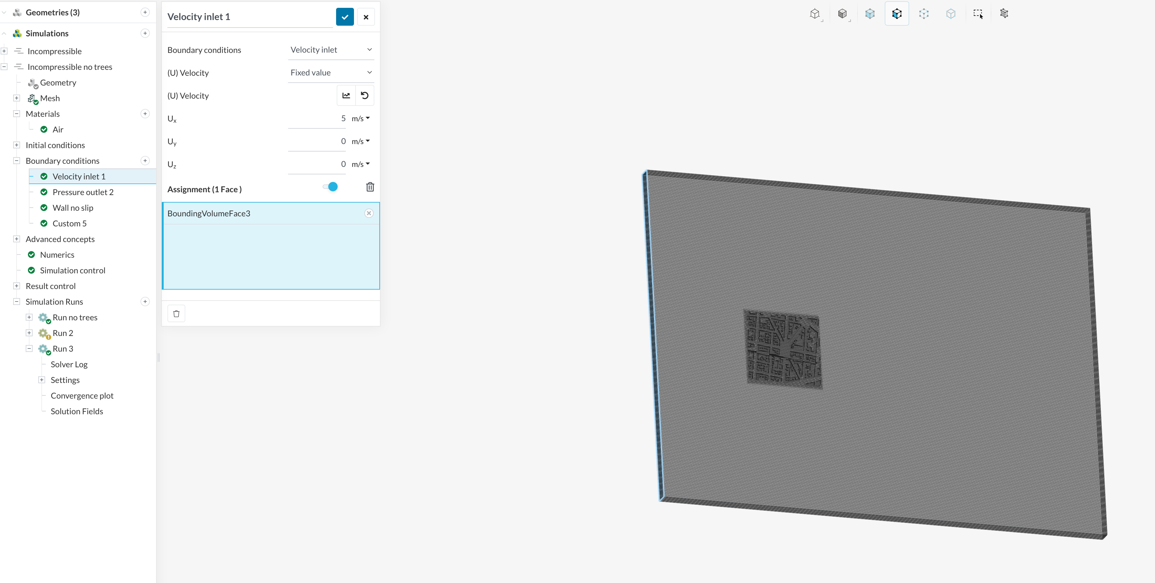
I did a wind study in an urban setting and set the velocity inlet value for Ux (westwind) to 5 m/s. Here is a link to the project, I also shared it with support.
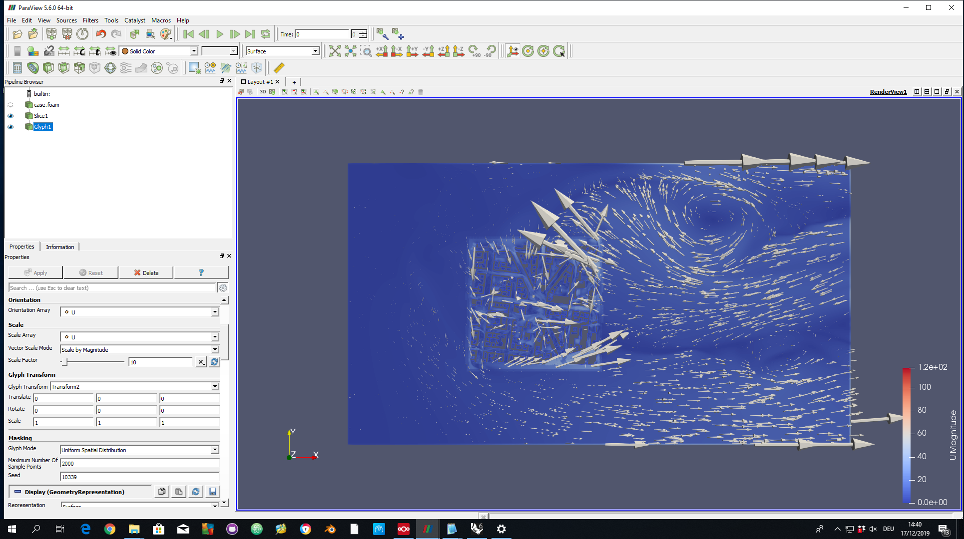
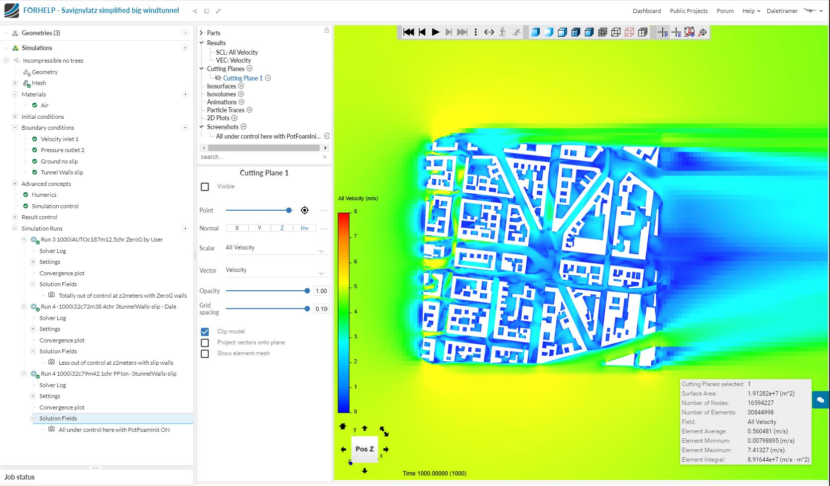
In the postprocesssed result the wind speed accelarates up to 110 m/s, which seems unlikely to me.
In addition, the visualisation of glyphs in paraview shows, that wind cannot flow out of the wind tunnel but seem to bounce back (see screenshot), even if I set a pressure outlet on the right hand side.
I would recommend adding an explicit wall BC to the floor, extend the domain in the z-direction and as far as I can see, there are no boundary layer cells established in your model. CFD Squad, what’s your opinion here? Anything that I missed?
By the way, check out existing simulations to get a feeling about domain size and meshing technique(s): Wind Comfort Projects
Thank you for your feedback. I updated the case like you suggested (larger wind tunnel / deleted both cylinders and circles, set explicit BC wall to floor).
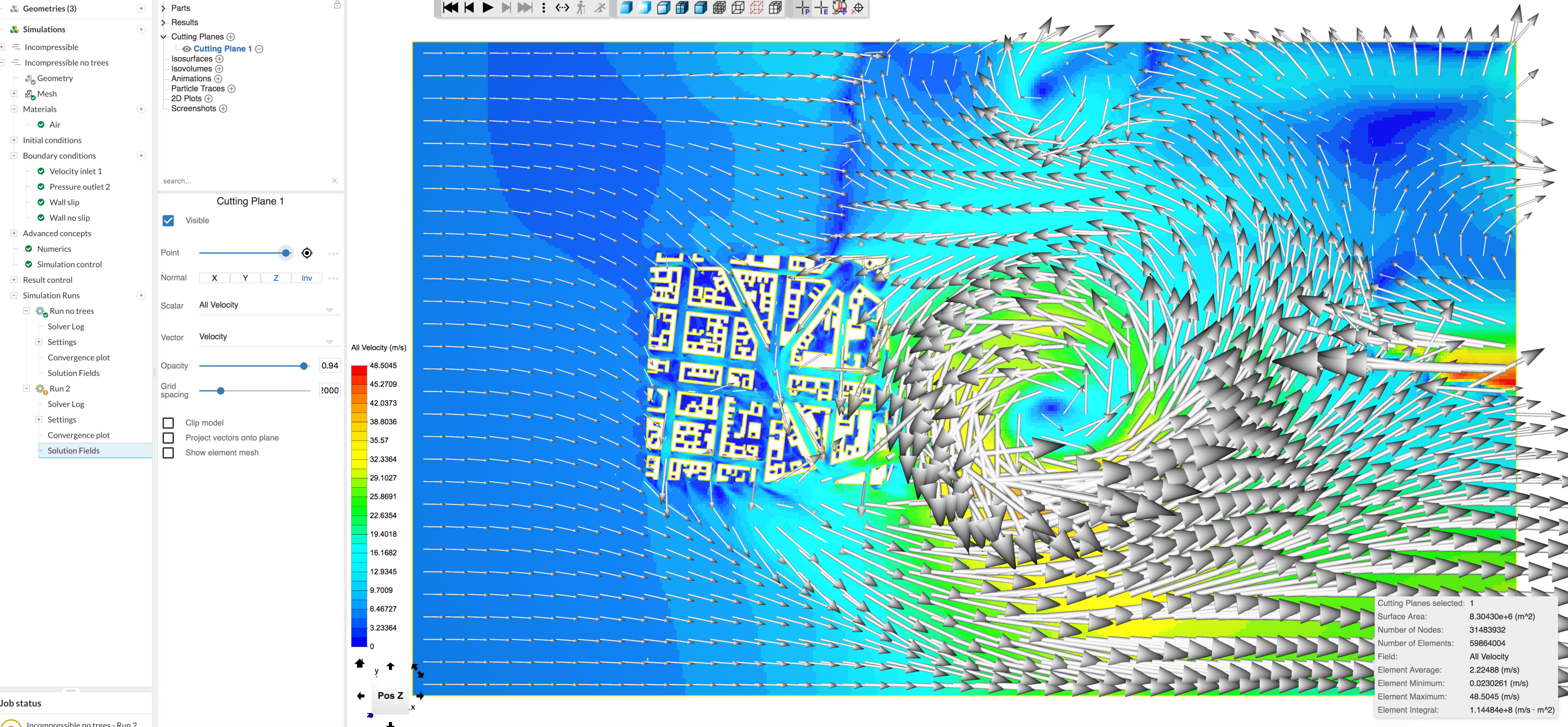
The simulation was stopped after write interval 700, because runtime was exceeded, however I wanted to share the result with you as it still seems highly unlikely to me. Please see screenshot attached. To me it seems like wind cannot “flow out” of the wind tunnel but bounces back and creates therefore a vortex.
Your BCs are correctly set, but in my opinion, your urban area behaves as VG (vortex generator). This is mostly amplified by your ‘tunnel’, which three ‘slip’ walls, reflecting pressure back to domain center.
If in Simulation control you put ‘Write interval’ to 100 or even 200, you will have snapshot showing the development of that vortex.
From Convergence Plot you can see that pressure divergence is not well reduced from step 72 already…
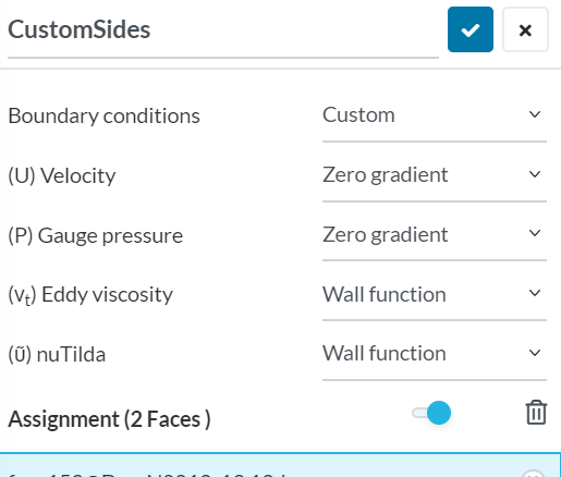
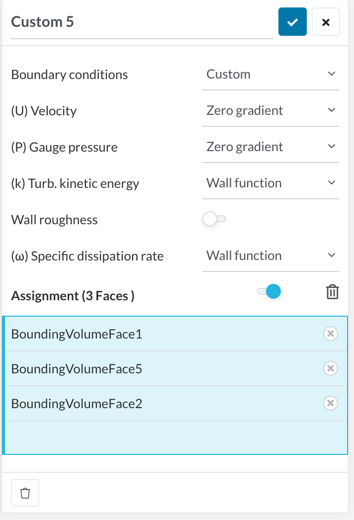
I would like to suggest to use ‘open air’ BC, which will be to set current ‘Slip’ walls as ‘Custom’:
Wow, you have achieved an apparent steady state image of a tornado, that was generated by your geometry in a partially converged simulation run, very interesting
Yes, as restam has suggested, the ‘Zero gradient’ BC’s can be used to lessen the need to increase your domain size… (I would still do a combination of moving the side walls about twice as far away from the geometry (inlet spacing seems marginally OK, outlet discussed below) AND use the Custom>Zero gradient BC on the side walls)…
As far as your outlet question about air bouncing off its face goes… Generally we place our outlets quite far downwind from the geometry to keep them out of the wake zone from the geometry. This allows the air to calm down and the solvers can more easily achieve the 0pa condition on that outlet face (I think that is what you used as an outlet BC) AND it will give you more accurate results… I would do a test at three times the space between your geometry and the outlet…
I did not see what you did with the top wall spacing… don’t have time to check your sim right now for that…
Then we can start to analyze your tornado, it it even remains…
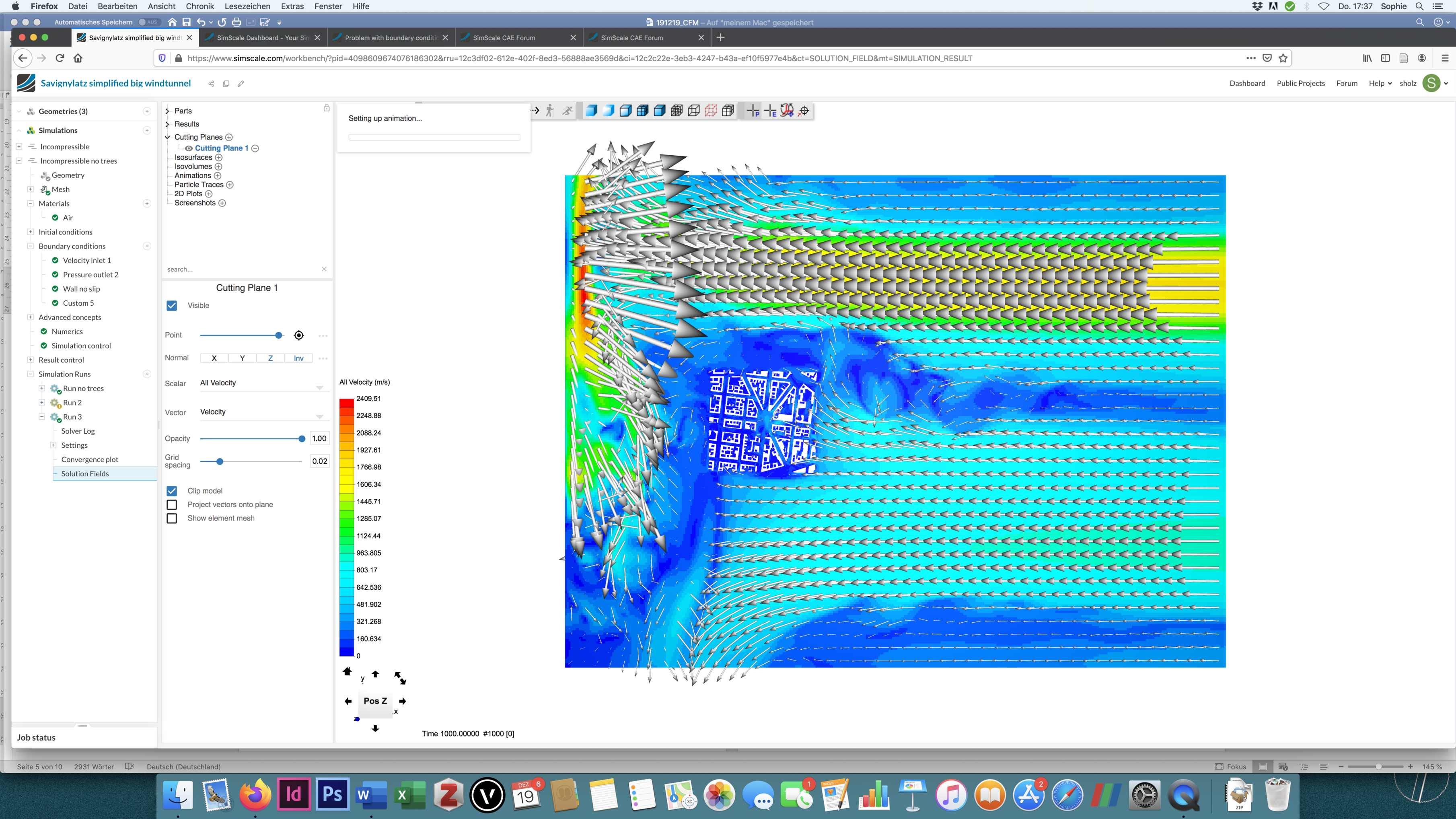
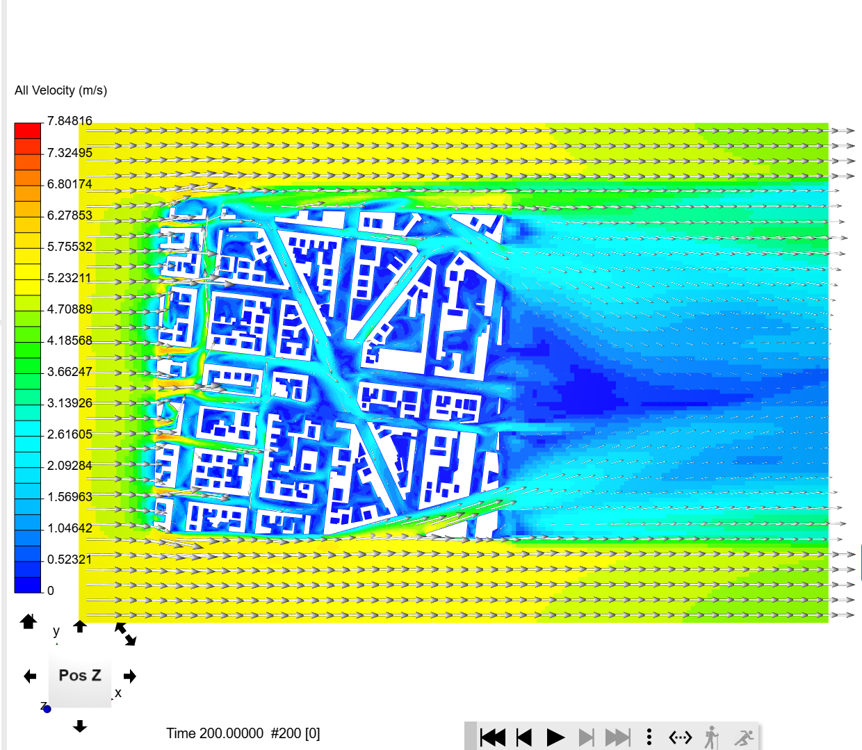
Thank you again for your feedback. I updated my project as you recomended: I increased the windtunnel (sides: two times of the geometry; downwind: three times of the geometry; top: six times of the largest building) and used Costum BC with zero gradiant for sides an top.
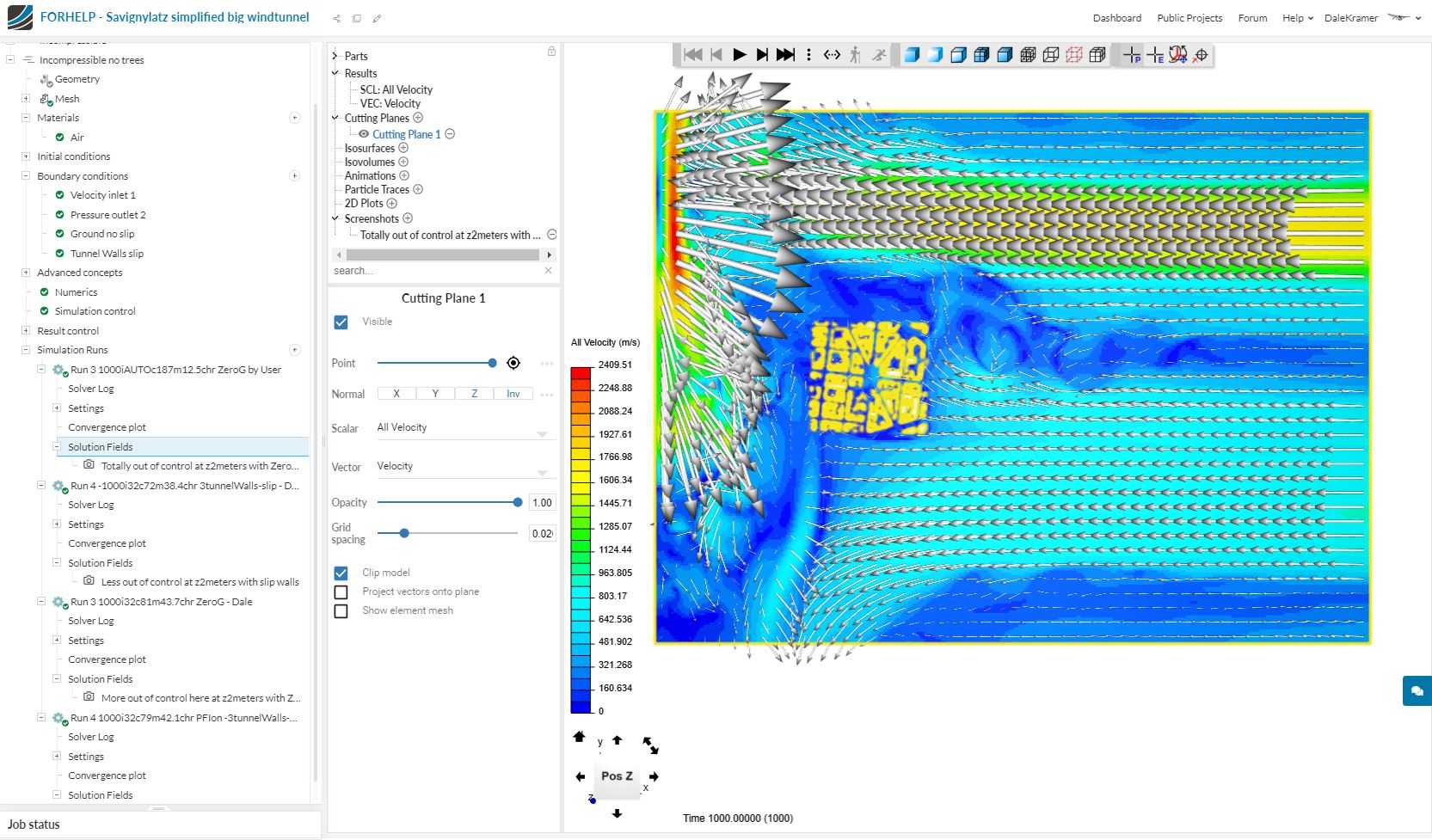
However, the result still cannot be correct. Wind seems to come from the right hand side, whereas I set westwind (left hand side). Also, wind speeds up to 2409 m/s!
Also, I know other people can remember how faces that are not specified as to whether they are slip walls or no-slip walls are treated… but I never remember, so by force of habit, I always specify all my geometry faces using a ‘box selection’ as no-slip walls… I doubt that is the issue here but I can’t see an obvious sim setup issue yet…
By the way, you are taking up many GB of disk storage for each sim run in your project by writing full solution sets every 200 iterations, I never write intermediate solutions, only at last iteration…
Hi DaleKramer,
thank you for your replay. Which 3 faces do you mean? The sides and top of the wind tunnel? Didn’t you recommend to set them to costum BC with zero gradiant, or did I missunderstood that?
Sure, I can change them back to slip-walls, but than I am back where I have been before, wouldn’t I?
I did other wind simulation before with the same BC setting (velocity inlet, pressure outlet, slip-wall at sides plus top, wall at buttom) and much smaler wind channels, and this problem never occur, so I am really curious, what the problem is here…
Actually Restam suggested to use them, I suggested that you could use them in addition to moving the walls out (I was hoping that in this case ZG walls would not cause problems instead of fixing them)…
I have had issues with ZeroGradient walls in the past so they are always potential suspects for me in trying to get a project back under control…
When I find things going wrong I always resort to basics.
The other recommendations I made were trying to rule out ‘easy to see’ potential issues and to maybe get your results to ‘seem’ under control…
Now that you have attempted them, and the project still seems out of control, you have really piqued my interest and I have copied your project and I am trying a few things out myself…
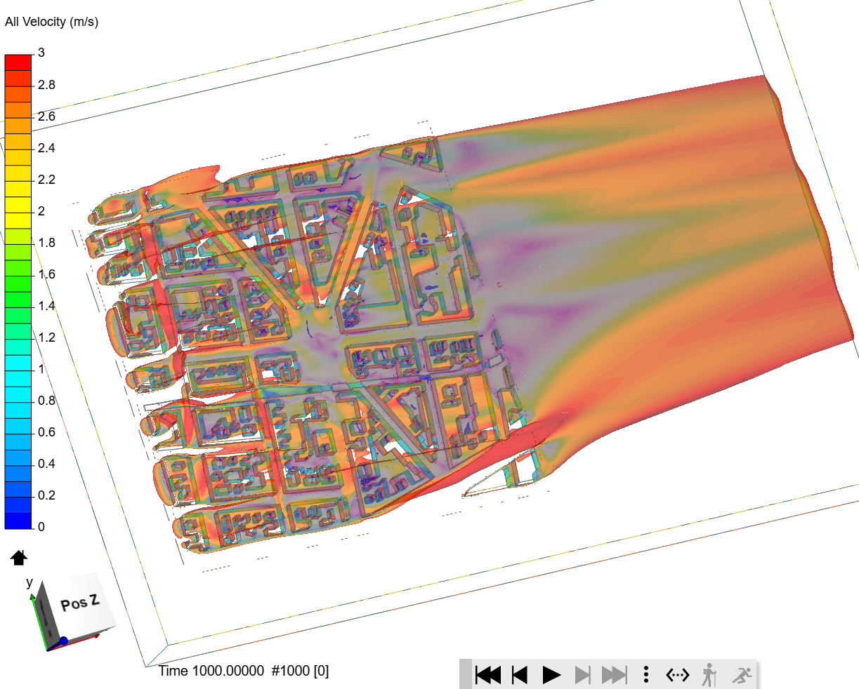
Well, I was curious as well. I did re-create it from scratch, using ‘my’ way of solving ‘free air’ simulation. It is still running, but the snap shot after 200 seconds gives already that:
.
.
.
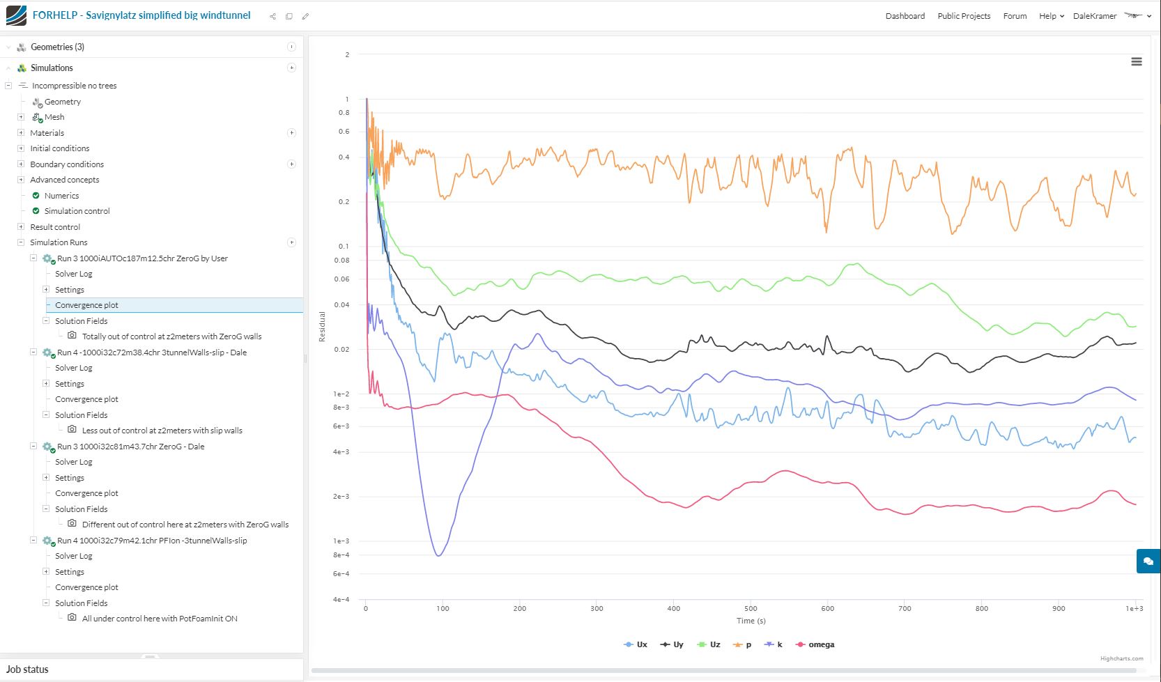
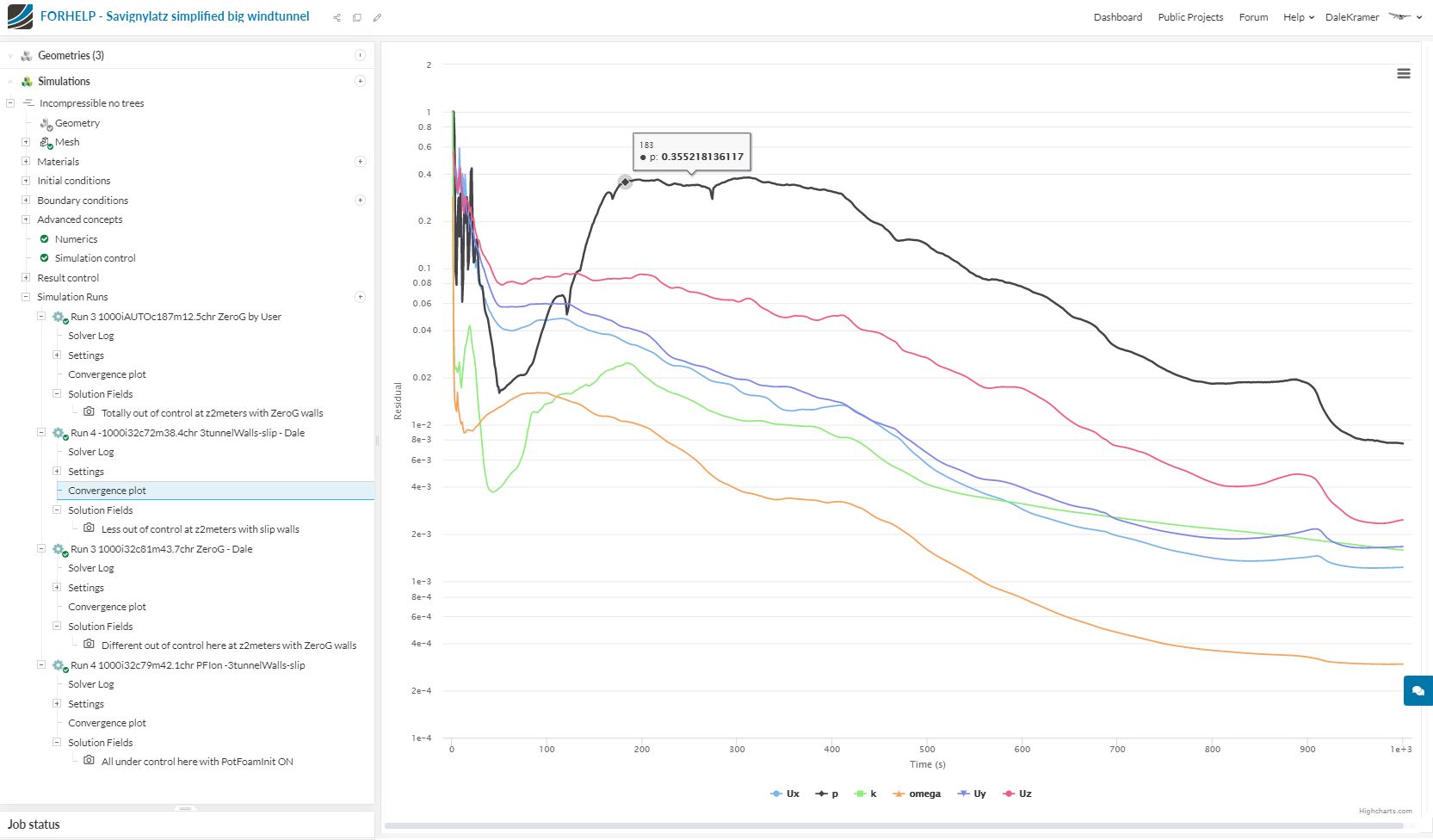
So my conclusion is that I was very remiss in not asking to see convergence plots of your images…
Basically you can not use ANY results of a sim run whose residuals are not adequately converged and if your results are not stable…
As you can see in my 1st run with the 3 tunnel walls as slip walls, the convergence was better and the airflow was too…
That gave me a clue to either run the sim to more iterations and see if the convergence is better OR do something that makes it converge faster…
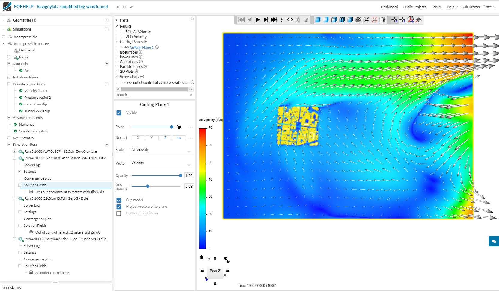
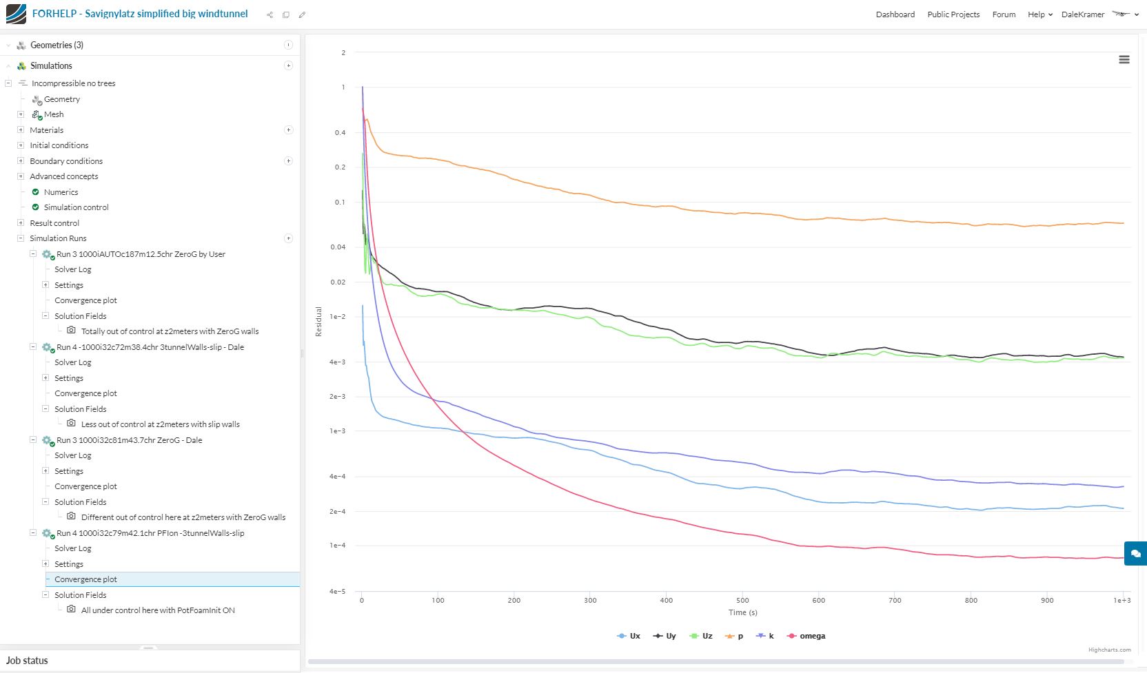
When I started looking, I saw that you were not using Potential Foam Initialization… I turned it ON, I did a 2nd run with the 3 tunnel walls as slip walls and low and behold the convergence was much better and everything seems under control…
You can take it from here
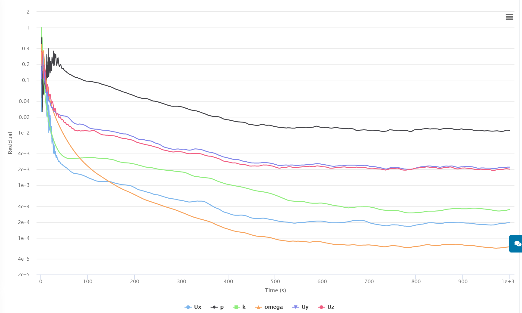
And I think I can conclude in this case that Zero Gradient walls take much longer to converge than slip walls… (if they ever will converge well) .
And for me, I think adding relatively few cells at level0 refinement to get no-slip walls further from the geometry is a small price to pay in order to NOT have to use Zero Gradient walls which I find take longer to converge and are quirkier to use in my sim setups…
My log file does not bark at you about wrong Schema used:
Time = 1000 smoothSolver: Solving for Ux, Initial residual = 0.000193543224795, Final residual = 1.18077664633e-06, No Iterations 8 smoothSolver: Solving for Uy, Initial residual = 0.00221466613444, Final residual = 1.67261898439e-05, No Iterations 8 smoothSolver: Solving for Uz, Initial residual = 0.00202661710653, Final residual = 1.92685541264e-05, No Iterations 8 GAMG: Solving for p, Initial residual = 0.0110003242897, Final residual = 9.87397722497e-06, No Iterations 6 time step continuity errors : sum local = 2.87717273754e-08, global = 1.12951051273e-11, cumulative = -1.5604542764e-07 smoothSolver: Solving for omega, Initial residual = 6.7577047335e-05, Final residual = 2.53042077711e-07, No Iterations 3 smoothSolver: Solving for k, Initial residual = 0.00034639052933, Final residual = 8.29504140426e-07, No Iterations 3
Exactly: I used anaphora in that conclusions, making ‘Zero Gradient Walls’ salient only in first sentence. Thank you for removing possible misunderstanding.
Thank you very much for testing the project yourself and for all your insight! I very much appreciate it.
Your results are looking really good and I will test both your approaches and will come back to you later.
@Retsam, Thank-you for confirming my assumption, and as you know me well, you won’t be surprised that I would like to try to combine both of our conclusions, which are now only related to the specific setups of each of our projects’ results…
Thanks for sharing your project with me yesterday and I am now on my new quest
I take it that you coarsened the pedestrian area region refinement, from Level 3 (1.25m) to level 1 (5m) in order to reduce the number of cells in your mesh simply until the wacky tornado’s could be calmed down, is that correct
Both Retsam and I did not fix your BMB layered faces to the ground face instead of the overhead Sky BMB face (zMax) which you had layered…
I assume that you really wanted to layer the ground BMB face (zMin) , can you confirm
Also, in that vein, I assume you mean’t to use absolute layering for the ground layers, since the ‘final layer thickness’ (FLT) of a 0.3 RATIO when used with ‘relative layering’ on a local cell size of 10m (all the ground cell sizes outside the city) would make a nonsensical (to me anyway) final layer size of 3m in the layering outside the city. At level 3 (1.25m) local cell size in the pedestrian area and and with relative layering and an FLT RATIO of 0.3, the FLT would be a more reasonable 0.375m and is what I assumed you wanted everywhere, so I switched to ‘Absolute layering’ in my continuation mesh, so do you want a 0.3m FLT everywhere (which is more reasonable to my brain) (yes it is weird that FLT is a RATIO when relative layering is ON and a size in meters when relative layering is OFF, but that is the way the ball rolls )…
And it seems that restam’s solution to calm down those tornado’s was to set the Div-ukw schemes to ‘Bounded Guass Upwind’ (BGU)… I strongly prefer to use the Potential Foam Initialization ON solution to calm them down, as the BGU divergence scheme is a 1st order scheme and will provide results with less expected accuracy the SimScales default 2nd order divergence schemes (regardless of the fact the, with default divergence schemes, the solver log ‘barks’ at you, as retsam has characterized those solver log warnings)…