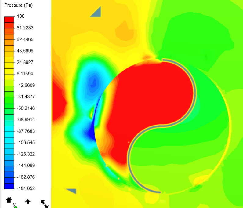
I am running a simulation for my Savonius Wind Turbine. After assigning the MRF rotating zone, and finished the simulation, the results that I obtained for pressure seems a bit strange. The pressure difference between the rotational zone and the outside of rotational zone is huge. Is this normal? Or something went wrong? Please help
Have you tried refining the outer mesh and increase the distance from your component to the inlet? Assume that this will have an impact on the results.
Looks to me like you are just not viewing down an orthogonal axis…
Try double clicking on the word 'Top" or whatever you see in the Axis orientation icon… (this would straighten that problem up, it it were the problem)
Could be wrong, I use ParaView mostly now… not sure if the problem I describe is possible in the SimScale PP or even ParaView for that matter
Well, to me it is a ‘known effect’ of mesh granulity difference between MRF zone / non MRF zone. Instead of going down with mesh size for all BMB (@jousefm suggestion), you can add a geometry primitive (cylinder) a bit bigger then your MRF. This would not make your mesh enormous and will smooth the transition.