Poor mesh quality for 15M cell mesh

Hi, so I’ve decided to do a quick n dirty CFD run on a F1 style wing I designed in NX.

When it came to geometry and mesh prep, I followed this tutorial (although went for a slightly bigger wind tunnel and refinement box size given the geometry difference)

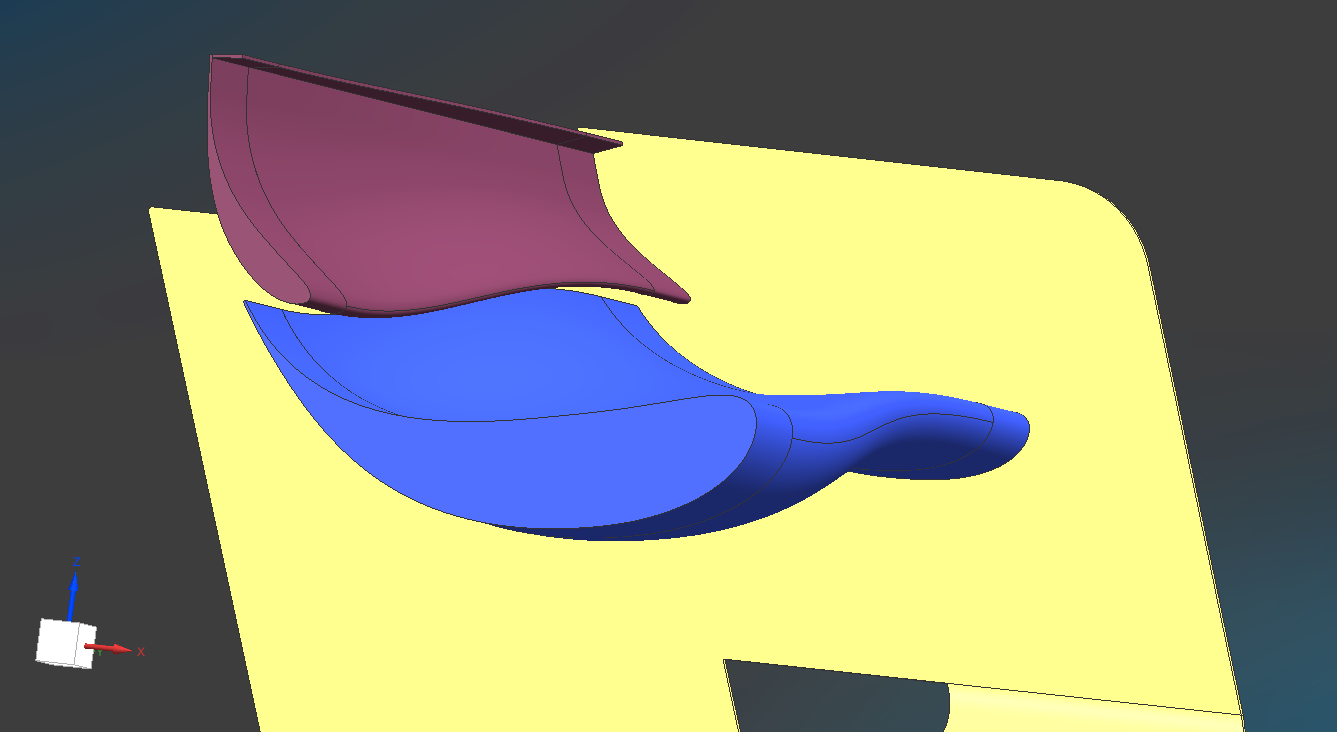
I uploaded my geometry as a native NX part file, consisting of ONE SOLID BODY (ie, designed half the wing, mirrored both profiles and endplate about the XZ plane, and then used the unite command on the original geometry and the mirror).

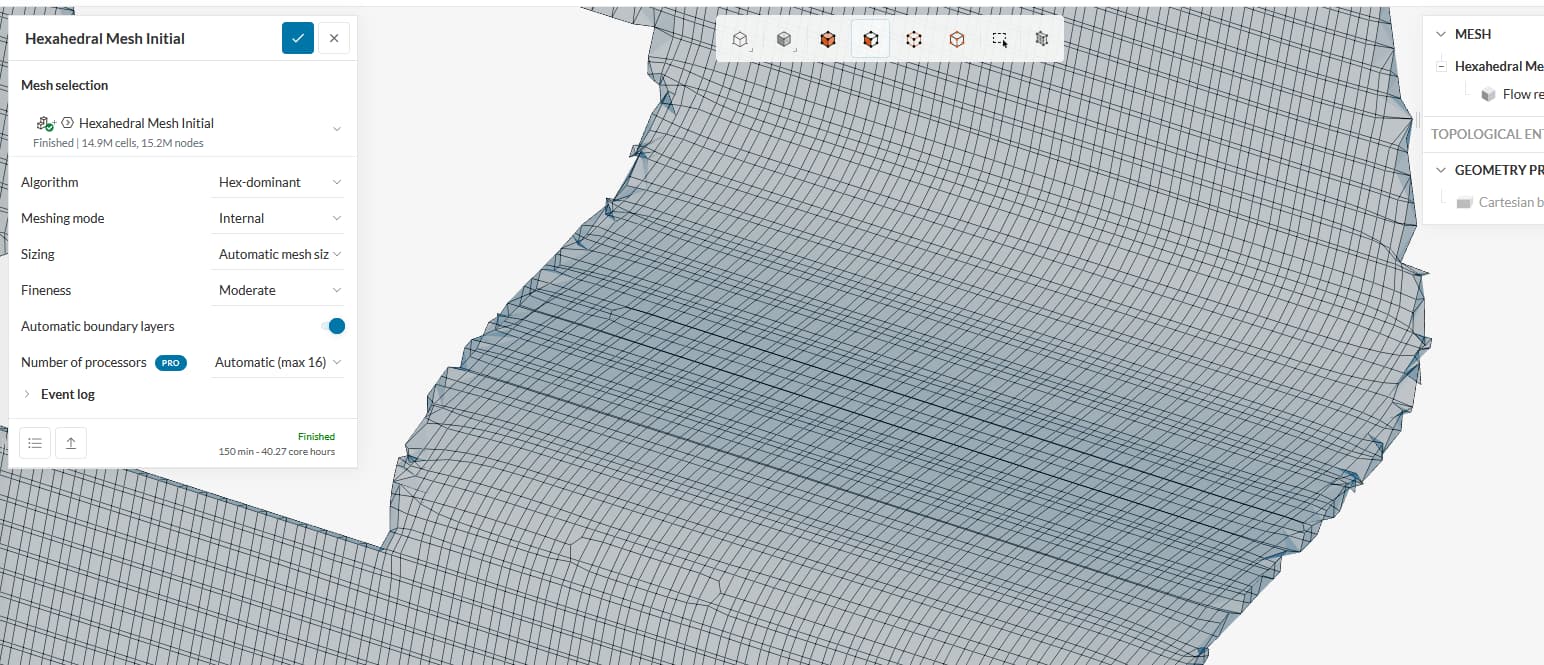
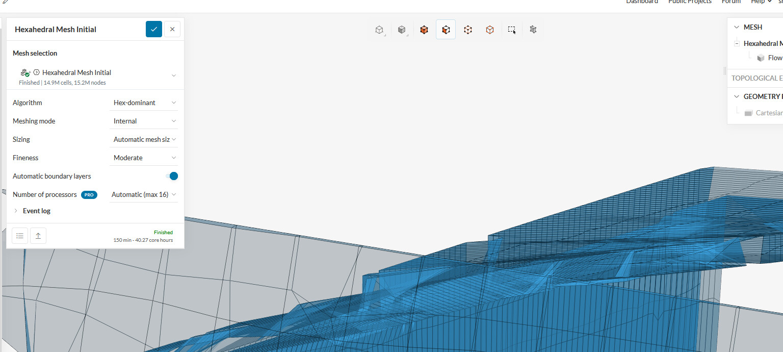
The mesh took 2.5 hours, with around 15M cells. According to the mesh log, it completed the operation without any errors however, looking at the quality its obvious its pretty poor.

Is this from bad geometry from the NX part? Have I done something wrong in the actual modelling? Should I have just kept it as a sheet body (surface) in NX? Should I of added back fillets for the gurney flap or added a 1-2mm fillet where the profiles meet the endplate to make sure they are ‘joined’?

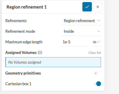
Do I just need to further refine the mesh in the area? 15M cells took quite some time just for the mesh to generate, so obviously refining further might waste more server hours and that’s before I even start an actual simulation. Should I of used the default mesher rather than the hex one?

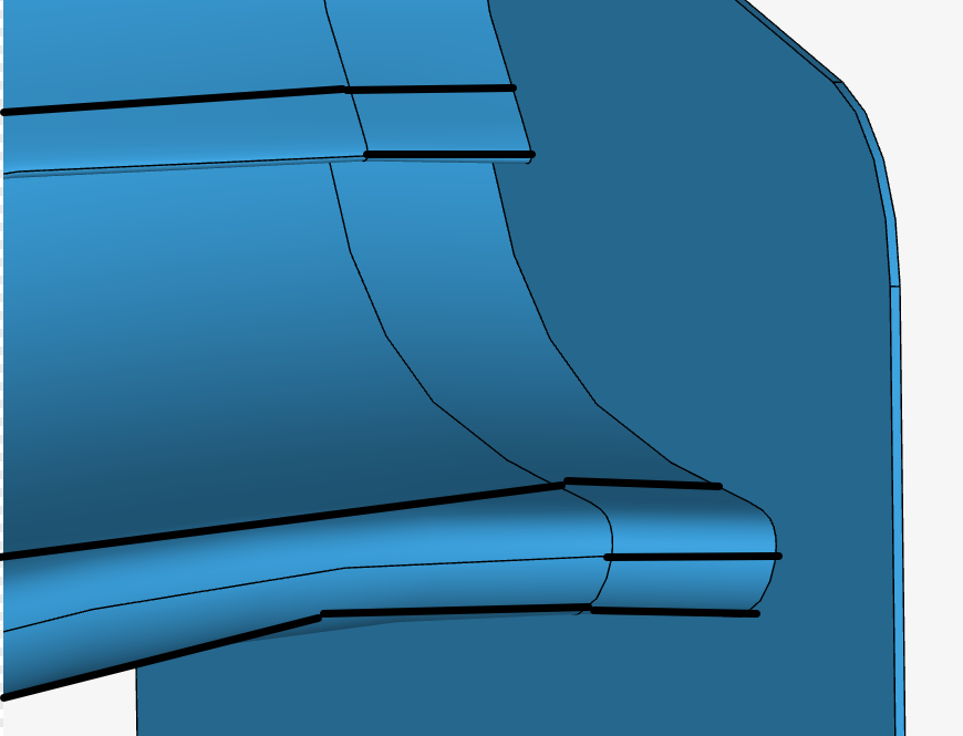
I’ve included screenshots showing the poor quality mesh on the aerofoil ‘surfaces’, as well as how the imported geometry looked like in SimScale, and how the part looks in NX.

I feel its best I get some answers/tips here before I waste more hours. I remember having similar issues like this back at uni when I was using Catia and Star CCM, obviously CFD isn’t my forte, and I should stick to vehicle dynamics instead…

Here is the project: https://www.simscale.com/workbench/?pid=4005625603842038505&mi=spec%3Ac354db21-5f2b-4bba-b7b6-763ec7b3e00f%2Cservice%3ASIMULATION%2Cstrategy%3A4


Hello shutchinson,

very interesting project and thanks for reaching out to us here in the forum.
At first, i would suggest switching to the standard mesher as it’s better in preserving features and creating boundary layers but the following tips are good for both algorithms.

Here are a few tips for improving the mesh quality and reducing the cell count.

In order to reduce the cell count, I would suggest using more refinement zone with increasing level of finesse.
I think 0.005 mm at your wing looks good.
so I would suggest keeping refinement level 4 at 0.01 mm
in order to produce good cells, it’s recommended to double the size of each refinement step.
This results in the following refinement regions.

Level 1 0.08
Level 2 0.04
Level 3 0.02
Level 4 0.01

In regards to the coarse edges even further refinements will be necessary in order to preserve the features.

You can use a local element size refinement.
I would start with 0.005mm but even 0.0025 might be necessary.

The same goes for the flap 1 Gurney.

Please let me know if this helped and how the mesh looks like.

Best regards
Sebastian

Hi thank you for your response.

So just to confirm then, you recommend to insert 4 refinement boxes as shown in your diagram, (i assume they would have the same dimension in the y axis as well, normal to the plane in that screenshot).

By levels, do you just mean the ‘maximum edge length’ parameter for that zone?

So for ‘box 4’ the most important area closer to the wing surface, the refinement zone settings should be like this?

Untitled6

For the global mesh fineness, should I leave it at 5, allowing the local refinements to increase cell count in the important areas that you just defined? I’m assuming around 15-20M cells should be what I aim for as a reasonable balance between calculation time and result accuracy?

Hello shutchinson,

so ideally the boxes would also decrease in size in the y direction. So box level for being overall the smallest and nearly just enclosing the wing,

For a hex mesh, it’s considered ideal, if from one fineness level to the other the cell size is halved. (growth rate of the cell)

With that the size for each refinmenent level can be computed as follows:
image

As for you box/level 4 seems to be good at 0.01m the other levels are calculated as:

Level 1 0.08
Level 2 0.04
Level 3 0.02
Level 4 0.01

For the global mesh, you can also start with a lower overall value. and increase if the gradient between the global mesh and region refinement is too big.

Please let me know if you have any open questions left.

Best Regards
Sebastian

1 Like

So firstly, thank you for your help so far, ran a couple meshes now and I’ve got one that is much much better than the original, my only issue now is the leading edge of the flap still isn’t captured completely smoothly yet. These screenshots are from ‘Mesh 3’ in the project, the last successful mesh run.


I’ve assigned a local element size of 0.003m to the wing surface currently, however, any attempt to lower it to 0.002 or even 0.0025, results in a error during meshing where the machine/server runs out of memory. I guess I could try 0.0027 or 0.0028. Or maybe apply the 0.003m refinement to just the endplate, and add another refinement that gives 0.0025m to just the two aerofoil profile surfaces, especially since they are more important than the endplate, and the endplate itself was pretty quick and dirty without any downforce/drag effect features like slots to reduce wingtip vortices etc.

Should I decrease the global mesh by one step to 4 or 4.5, and then try get the local refinement on the wing surface down to 0.0025? For what it’s worth, the trailing edge of the main element is 1.5mm thick, and the gurney flap on the upper flap element is 2mm thick, and about 18mm. Flap chord is around 135mm and main profile chord is 320mm at the wing’s center which is the longest section.

I guess before I ask my final question, I should explain my reasoning behind the simulation in the first place. Basically I created the wing as a way of learning NX at home (was taught Catia at Uni), with the intention of then doing a couple nice realistic renders in Keyshot to then show my mate etc, as a result I’ve focused the wing design more on aesthetics than outright downforce hence the ‘spoon’ wing I like the look of, despite it being a medium downforce setup.

I was also trying to explain to my mate that most of the popular aftermarket rear wings you can get for your car aren’t even all that good as most of them just reuse NACA profiles that were designed for aeroplanes, as opposed to bespoke profiles that are designed with much higher camber and much lower aspect ratios etc, not to mention you can’t just take the values from their CFD as gospel, as even if their CFD was very accurate, that won’t reflect real world scenarios and there’s no substitute to real data gathering and track testing etc.

So with that out of the way, my only goal with this CFD run is to hopefully show to my mate I’m not talking rubbish and show my wing is producing more downforce than a popular aftermarket wing for which their CFD and data is on their website.

Their peak downforce number was for a 160mph air speed, which is what I’ll be doing. So with this in mind, and especially with how aggressive the camber is on the central section of my wing, how important will capturing the boundary layer be and getting a proper y+ value depending on the turbulence model I choose? As I imagine with the high Re number and aggressive camber, there is a chance I might get some flow separation on the trailing edge of that flap and would still like to get a result that is somewhat representative even if its just going to be shared between me and my mate who doesn’t even know anything about CFD or fluid dynamics etc.

Here’s the project again:

Hello shutchinson,

I would suggest ou to create a feature curve at the leading edge as well as splitting up the leading edge faces. in order to assign a local region refinement just there.

In regard to your second question. As you mentioned CFD will never be 100% accurate. That’s, why we will always have to make, comprises between accuracy and runtime.
In regards to y+ I would recommend to aim for a low +y (+y <3) mesh.

For this, you might need to add some more layers to your BL to receive a small first layer height, Whis will increase the cell count. therefore I would recommend to reduce the complexity of your CAD geometry.
For example a basic straight Endplante will work totally fine in your quest to achieve more downforce, and will require much less computational cost :slight_smile:

Best regards
Sebastian

Hi, so since my last reply, I’ve done a bit more reading and regarding the prism layers and the BL, it seems like trying to target a specific y+ value isn’t as important as making sure my prism cells completely enclose the boundary layer. The only difficult thing now is to find a sensible value from literature to get a rough estimate of boundary layer thickness on an aerofoil at high reynolds numbers but with flow velocities below Mach 1, from there I can chuck in a few lines of code in MATLAB to determine initial growth ratio and number of prism layers as a first guess, while still keeping an eye out on the cell count of course.

I’m assuming for a 160mph flow on an aggresively cambered aerofoil, 99% flow velocity will be around 1-2mm from the surfaces, assuming the flow does remain attached on the main plane anyway, I have a feeling my flap is a bit too extreme.