Hello, CAD mode errors have been treated and now it is time for simulation runs !
I am modeling the behaviour of the shock absorbers of the PHALANX CIWS during operations in three scenarios , one shot , a burst of 100 shots and finally a 1500 shot burst (runing out of ammo scenario).
A frequncy as well an harmonic and dynamic analysis must be done.
I would like some advice / guidance on the following 
-
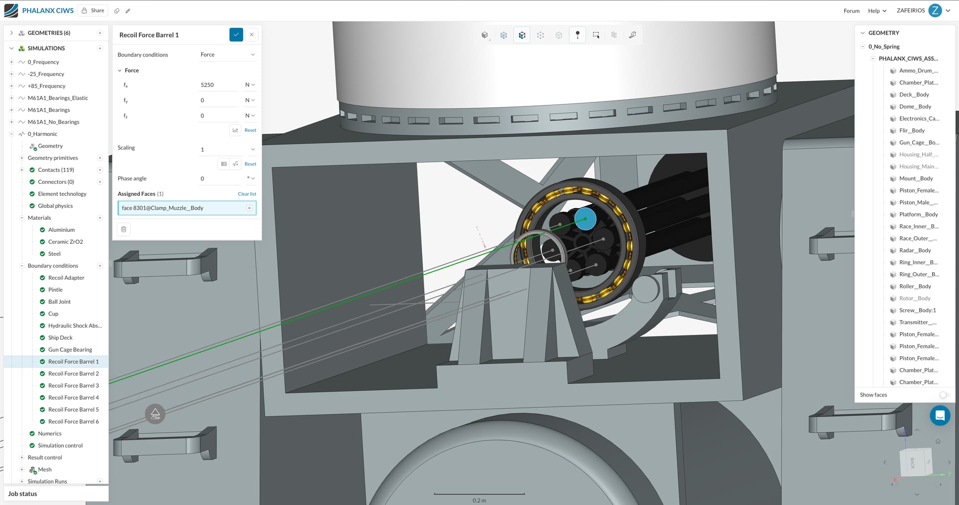
The modeled M61A1 Assembly has an eighteen double row angular contact ball
bearing and a needle bearing of 36 rollers that hold the rotor shaft. Is there any way to model the bearings counterclockwise movement ? (Till the moment i have applied centrifugal foce on rotating parts and the corresponding sliding contacts)
-
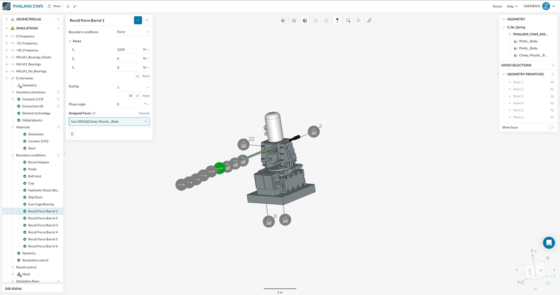
In the firing scenario projectile recoil force has to be taken in consideration, on the single shot i guess that applying the force on the firing barrel bottom as well as the corresponding face of the rotor locking lug is enough, but what happens in the 100 and 1500 burst scenarios?
-
The 4 hydraulic shock absorbers are initially modeled as a male and a female piston getting seperated with an elastic support , after getting the measurements on the absorber force that is applied on the pistons faces we are going to examine a hydraulic shock absorber
The overall concept is studying the shock absorbers distribution on gun dispersion at the 75 Hz frequency (resonance risk - gun rotates at 4500 RPM)
Hello all,
I am making a project on the vibrations that take place on the PHALANX CIWS during real life engagement scenarios and how the vibrations affect dispersion (barrel tip displacement).Ultimately we suggest a better way for vibrations handling.
The PHALANX CIWS, is armed with a M61A1 Gattling gun (6 barreled). It shoots in 2 paces, slow mode (3000 Shots per minute and fast mode (4500 Shots per minute).
An initial frequency analysis has been done , and the eigenfrequencies have been estimated on both 3000 SPM and 4500 SPM. Also the gun traverses from - 25 to +85 degrees vertical (eigenmodes and eigenfrequencies have been estimated in 0, -25 and +85 angles)
Harmonic and frequency analysis must follow.
Supposing the gun rotates and fires , how should the force application be modeled to capture the rotational effect scenario ? Centrifugal force has been applied to the rotor and generally all the rotating components. The barrels fire in sequence and a recoil force has been applied to the bottom of each barrel, though I am not sure if it captures the real life behaviour.
Hi @Zaff_Zaff, thanks for posting!
Your overall approach looks good to me. I think you could run a harmonic study and apply a sinusoidal force to one of the barrel’s faces (to account for it’s rotation). Then just apply a centrifugal force to the whole rotating structure and you should be good to go.
Another alternative would be to actually rotate the barrel in a dynamic study using rotating motion and compare the results. It certainly would look very cool at least.
Cheers
Igor
Good evening !
Well actually i am trying to find out the distinctive diferencies between harmonic and dynamic simulations.
Please i would like some more explanation on the way you suggest the harmonic study should be conducted, why the force should be applied only to one of the barrels, also is there any special field/way fot the application of the sinusodial force to be done ?
Hi @Zaff_Zaff, I’ve explained some of these in your other post. As to your first question
Basically:
- Harmonic
- Sinusoidal loading, linear behavior (no physical contacts for instance)
- Dynamic
- Time-dependent loading you can insert via a table (not necessarilly sinusoidal)
- Allows for non-linear contacts
Cheers