recently PERRINN F1 team started to use SimScale as the primary CFD platform.
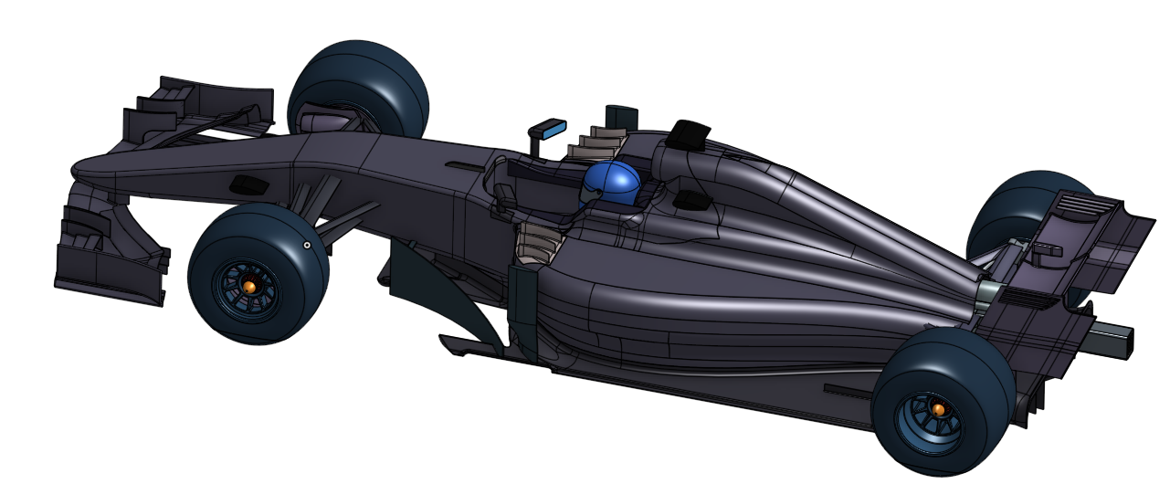
PERRINN F1 is a project in which a Formula 1 car is designed. All of the data that is created in this project is open source. The geometry is available on OnShape as a public project:
All of simulations on SimScale will also be made as public projects. Just look for PERRINN F1 in their names.
If you are interested to join us visit www.perrinn.com and leave your email address. Everybody is welcomed. If you have any questions do not hesitate to ask.
thanks for sharing the data. As an expert in OpenFOAM, numerics and all related stuff, I am interested in two points:
a) Do you want to get data out of the simulation or is it just a test if it is possible to do something like that
b) How will you model the weels ? Static or will you apply an AMI (arbitrary mesh interface)?
Hi @akosior - excited to see the PERRINN F1 car evolve with Onshape and SimScale :)!
Hi @TobiasHolzmann - @akosior already ran a bunch of sim projects of the F1 car that you can see over in his profile: SimScale. You can directly open them and check on the sim setup. We’re right now implementing some additional features that were discussed in other threads to enable the next steps in terms of CFD analysis for the PERRINN project!
when we sort out some correlation issues that we are having right now we want to use the results obtained on SimScale in the design process. When we are there I think that AMI will be one of the options that we will try for wheels.
I dont think the current wrong wheel tread separation has got anything to do with not running MRF. Wake characteristics of a rotating wheel in contact with a moving ground is closely related to the contact patch shape and the two main vortices, how the two main vortices alter the downwash, which reflects the tread separation. Or, if you look at the the other way, it is how the wheel rotation (mainly the tread surface rotation) alters the tread separation point, which in turn changes the downwash and therefore the two main vortices. We should and will get the tread separation right without MRF. Simply applying a rotating wall on the wheel can and will get the wake features.
If I may suggest, before dealing with the tyres there’s a couple of things than can be easily fixed and will improve both mesh and case setup:
Rotate the geometry (0.4946459 degrees) in order to get a completely horizontal floor. This is also applicable to any CFD software you might be using such as STAR-CCM+ or Fluent; and is something we always do at work.
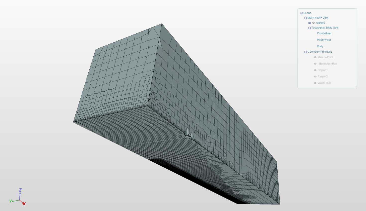
Get rid of the wind tunnel from OnShape and, instead, use the _BaseMeshBox to define the tunnel. This follows the rotation of the geometry and will help you to get rid of those nasty cells in your mesh.
Yes, I assumed that; we get models like that constantly at work. Though CAD designers find it more convenient to have a horizontal body; we (the CAE side) prefer a horizontal tunnel so we end up rotating the whole thing. By geometry I was talking about the vehicle in particular (and the tunnel if he wants to keep it). Doing so, you avoid using trigonometry to input your initial and boundary conditions and get back the drag and lift coefficients referenced to the tunnel’s reference frame (which is aligned with U_\infty).
you are right about the rotation and the reason it exists. But we decided to keep it tilted for a bit different reason. Our goal is to have multiple people working on a single public document in OnShape and multiple people importing it into SimScale. In order to rotate the geometry you would have to make a copy every time there is a change in the main project and let everyone know about this new file. It just is more error prone. In our way the box is created once and you calculate the initial conditions also once so that is not a big effort.
You are also right that the mesh would be better using _BaseMeshBox. But my solution here is to be able to define it using 8 points instead of just 2 (they are transformed to 8 points in the blockMeshDict anyway). Then the box could be tilted and the mesh on it would be correct. We already asked SimScale for this option and they are looking into it.