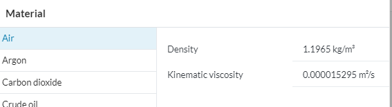
The values in the calculators are the non-existent so far as i know because the values all come from the tutorial, which is based on a car going 20m/s. I assume the air density and kinematic viscosity numbers are taken from simscale shown here
thats pretty much all i can say as i dont know the length they used, although all FSAE cars are around 3m long and i dont know what Y+ they were going for.
The Y+ graph u made looks awesome, and the U plot as well
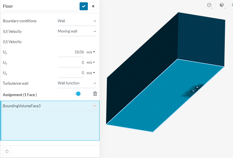
The road surface isnt 0 because its a moving floor, to simulate a rolling road in the wind tunnel.
Why are you suggesting Y+ at 50 and not 30? isnt this outside of the log-law region?
I personally would do the tires as they do contribute to a decent amount of lift and they create a lot of turbulent air for wing elements later down the car.
I agree this is worth it, not only for the results but for my knowledge of CFD, and for anyone else that reads this post.
18m/s was taken from our teams lap time simulations which are based on the FSG track and has average speed of 18m/s. I was unfortunately alone in designing the aero package from last year (no other teammates to help) and i didnt have time to simulate under many different driving conditions. So i elected to develop the aero package at 18m/s in a turning condition at that speed. This resulted in mainly roll and tire angles which i simulated as well.
Also yes 18m/s (~60kmh) is fairly slow but our top speed (track limited) is about 120kmh. The FSAE competitions are all designed for high grip (other then the acceleration event) so downforce is the main goal. Drag is always a factor but is outweighed by the many lower speed turns, plus DRS is an option if you have time to build it.
This results in the need for a very dynamic analysis of the car under many different driving conditions, which creates an “aero map” and is the best way to get good overall results and overall score from the design judges.
It was also the reason why i created the dynamic solidworks model (i have the instructions for this in another post) and why im doing my thesis on this topic.
Thanks so much for your help … as always the guru provides
With all this effort you are putting in, I suggest you fill in the calculators with your values as a learning exercise and show it to us.
Also, I do not like SimScale values for air density and viscosity. I suggest getting that data for a temp and altitude that matches more realistically your test track conditions…
Even as a moving wall, the velocity at the road surface should be 0. yPlus should also be 0, except in areas where the air that is disturbed by the car, hits the road… We will have to understand why velocity it is not 0…
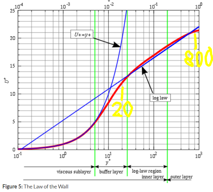
Here is the Law of Wall plot that seems to be most quoted:
From my experience and from just looking at the graph, the log-law region where the red and straight blue line most closely match goes from Y+ 20-800 (yellow numbers added by me)… Below y+20 shows much more error%fromRED when using the straight blue line than for 20-800 (and even 1000)…
Also, from my experience, for more complex shapes, you almost always end up with an ‘area average’ y+ that is lower than you aim for, even if you do multiply cell centroid distance by 2 for 1st layer thickness from those relevant calculators…
Well, then you are unlikely to need this degree of layering preciseness on much more than the major surfaces and a downforce wing, if you put one on…
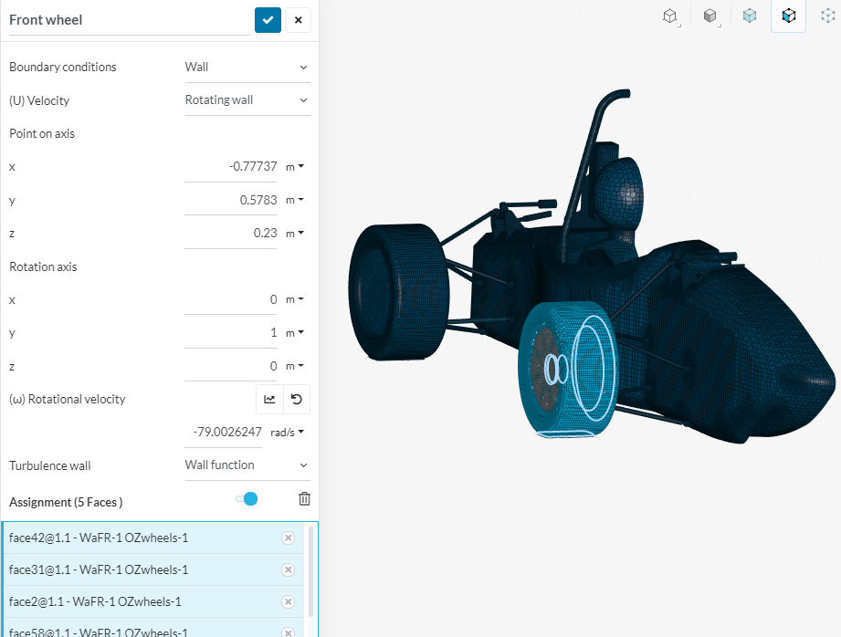
PS I also find it interesting that your wheel MRFs only seem to encompass your spoked wheel rim components, perhaps that is due to being mostly interested in downforce…
I did this simulation partly because you were interested in the Y+ for this section of cells, and mostly so that i could see where we were last year with incorrect meshing and compare to our new method. I also have been learning a crazy amount through this process and documenting, even the wrong way, has value to other teammates.
I will be changing the density and viscosity numbers when i do my official simulations with full aero, as I the timing of my masters forces me to do the real world testing in late march. As of now i still want to compare to last years numbers and get a stable mesh process.
Ah you mean it should be at 0 directly touching the floor because the air shouldnt be moving (viscous sublayer). Im not sure either why this would happen.
I have seen this graph but didnt look super close at the actual values. I have just read from multiple sources that the log-law region is between 30 and 300. I did however read that Y+ values should be a bit higher then 30 so that you dont risk taking values from the buffer layer. So i will stay with your expert opinion of a Y+ of 50.
You are probably right that i do not need this level of detail on the main car. The main areas of interest are the wings, however i wanted to learn on a smaller model to save core hours.
The MRF zone size from the turorial are encompassing mostly just the spokes of the wheel, so i just copied that method. If i go too big the zone will touch the motors and I dont want them to move.
I will be runnning a new mesh and sim with your method today so we can finally get some useful progress.
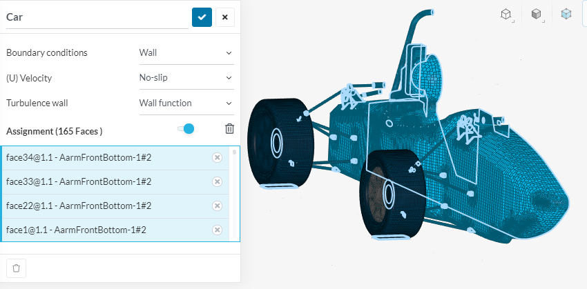
As I look at my Uplot this morning, another thing that needs investigating pops up in my wacky brain, why are the wheels and tires surfaces, not at 0 velocity, I assumed that they should be no-slip walls too???
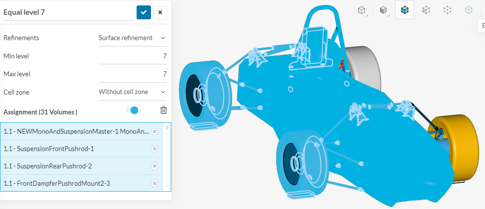
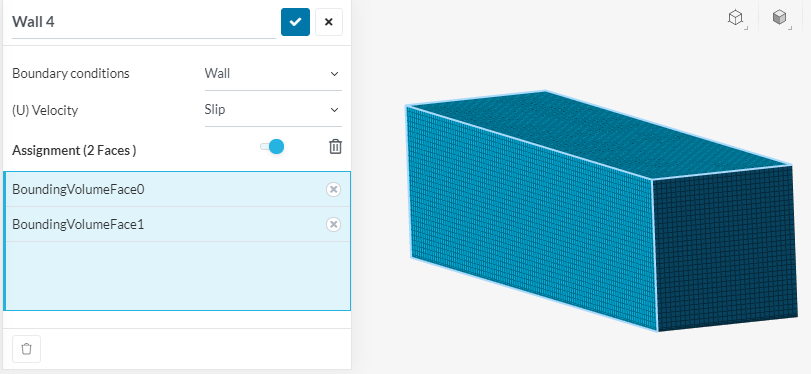
It would really help if you had assigned a bunch of ‘Topilogical Entity Sets’ to your geometry… This would make it soo much easier to figure what faces you have refined and put BCs on
And, my brain wants to know what percentage overall vehicle drag is caused by the roll bar?
Never hurts to fix BC setup errors and add results items as you go while you are optimizing y+.
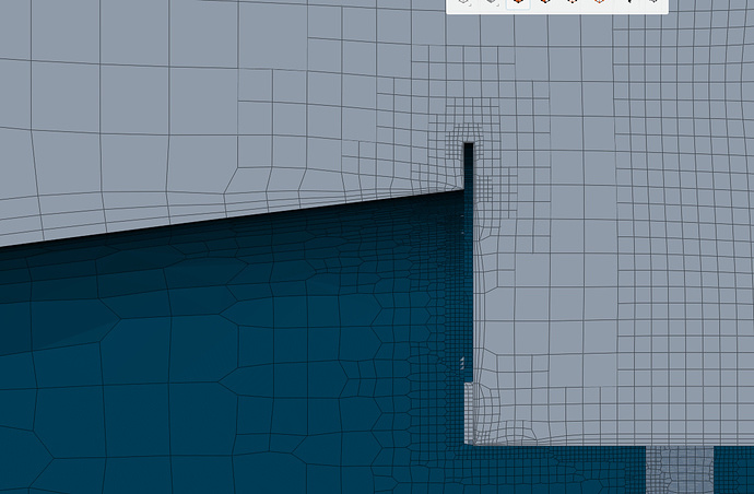
And, it appears that little lip, in front of the upper front suspension links on your body, and which you are zooming in on in order to show layering issues, is doing a nice job at deflecting the air flow, and it is keeping those suspension components in low velocity air (at the vehicle centerline)…
I would add a forces results item on those lip faces to see what drag force you get while deflecting that air so nicely…
Maybe the wheels and floor arent at 0 velocity because the viewer isnt showing the surface speed but the moving condition assigned to it. and any variation you see (change in color) is the change in velocity in relation to the preset condition, in our case 18m/s.
Yes i havent used or even knew about topilogical entity sets but i assume they would save some time if the meshes are the same between sim runs, which they wont be in the future as the car will have different roll, pitch, yaw, and tire angles. For now i ill add what refinements have been done.
For the roll bar i assume on the next run i can add a forces and moments measurement to just the bar if your interested:grinning:
Do you mean editing the previous posts to give correct BC settings? Because i might leave that until i make a complete new tutorial post of the correct method that Jousef wanted at the end.
Yes that area of the foot pedal cover was designed as a large “gurney flap” to push the air over. It does seem to be working well, it was made by my teammate Jonas the new chief developer of Aero for this year @Raceyard53
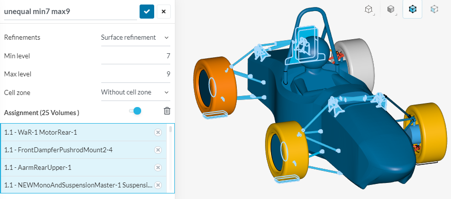
It would but i believe the way the mono is constructed it is all one face. I wanted to add your unequal Min Max levels to this area but i am unable to select it. I could upload a new geometry with this foot pedal cover area as a second piece but for simplicity i think i will leave it.
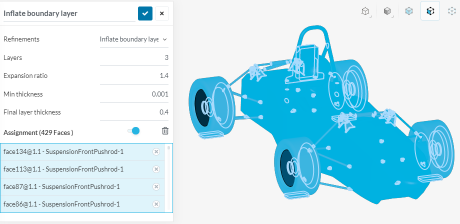
Im about to do my next mesh, would you recommend not adding boundary layers to small areas (suspension beams) ? i think the wheels need it but all the suspension parts, main hoop, motors might not be necessary to add.
Ok, but until numbers are commented on, I consider them fair game for editing, especially if they help for someone following later (and especially if they aren’t in line with recommendations)…
This may be one case for splitting surfaces of a solid even though I generally do not like doing that…
My little experience here, wrt layering on small details in low velocity air, would make me consider not generating BL on them now (revisit that decision later)…
But that will make it much harder for me to create accurate ParaView and yPlusHistogram y+ analysis for you (because then I have to select which faces (of hundreds) that were actually layered by you, so I may not have the time to do that)
If your postulation is correct (and it does not explain the non-zero velocity on tire surface which is outside MRF), then I am very worried about whether force and coefficient results are accurately calculated for moving walls and MRFs
I have not used or analysed in detail, moving walls or MRFs before so this may get interesting
Even if a geometry, that has a large number of faces, is meshed only once and has only one sim ever created for it, I find it is faster and tidier to make descriptive TESs for groups of faces on the geometry
if you believe that there will be problems with not adding a boundary layers to everything then i will leave it as is. You dont need to be doing work for me though, even though i really appreciate it.
The 0 velocity problem i have no idea on, but i also hope that getting inaccurate results due to this are minimal enough to not effect anything. As you know, the most important areas are the wings and there are many parts on this car that have a minimal effect on the results.
i will use the topological entity sets in the future if you think this is worth it (dont worry i trust your judgement on everything).
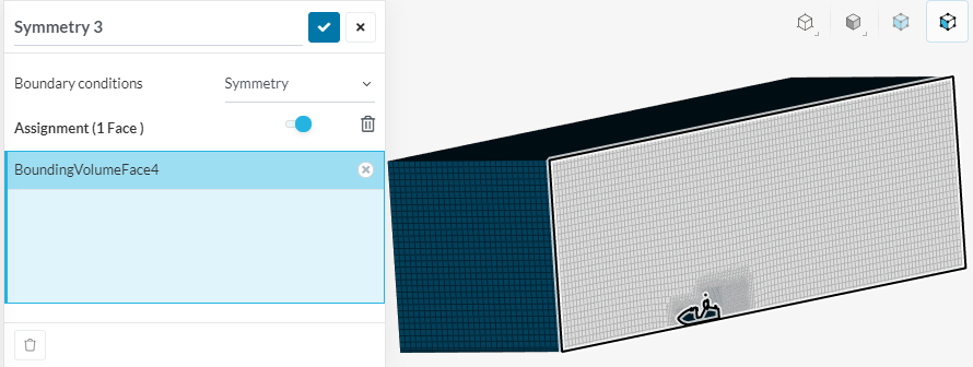
I have lots of detailed research which I have done as to which BC should be used on the BMB symmetry face and I can highly recommend that you do not use any symmetry BC… I recommend that BMB symmetry faces simply be set to ‘slip walls’…
Aha, this explains something and it will mean that the total area used in my y+ analysis was potentially incorrect…
I always include all my vehicle faces in boundary layer generation, I have seen no reason to ever leave any vehicle faces out of my layering domains until I saw that for you, there MAY be reasons not to layer faces in low velocity areas in order to reduce number of cells in a mesh and to reduce meshing development time BUT only if I had proven to myself that NOT layering those special case faces would make little difference in the results…
So for now, I revisit and I think you should layer ALL car geometry faces as I certainly expected that the wheel and tires were being layered since they are in high velocity flow…
I think leaving the boundary layer on everything is the way to go, its much easier. And larger total cells are mostly increased by region refinement level and size.
For the symmetry face problem, it is only for these “setup simulations” as the real ones where i will draw and compare results to real world testing data will all be full car turning simulations. Which is why total cell amount is a topic. Currently im around 6-7M cells without aero. with areo i expect 11-12 million for half car which means 25-30 million for full car. this is acceptable but moving to 30-40 would most likely result in memory issues with only 32 cores available. I remember last year at about 25 million, i had issues and had to reduce level refinements to complete the mesh.
And another aha, since you are unable to select the faces of that lip individually in your geometry, then that lip will not be retained/layered well in your mesh that uses my recommendations… (I mean without resorting to a dreaded feature refinement)
Yes and i feel that this applies to other areas as well. Its crazy how much you have to understand with meshing just to get the geometry right. If i wanted to use your method, i would have to model the car to exactly for what my finished plan was for meshing, which can only be done after understanding everything with how meshing works.
I am running a mesh now, they only take about an hour so well see how that goes. I posted the refinements used before, but no feature refinement on this run, I can do another exactly the same but with feature refinement.
I use both, but I generally get higher area percents layered with ‘relative’ at the cost of it being harder to precisely stay in the y+ 20-800 range or the y+ 0.1 to 8 range…
Perhaps you will try both and report results differences here
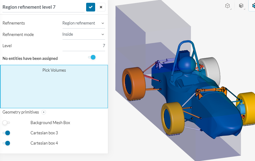
i have done 2 simulations. one without feature refinement level 7 everything and level 7-9 on suspension and now one is running with the feature refinement and only the level 7 on everything.
However the level 7 region refinement is killing the cell count, its at 12.8 million which is way to high. The boundary layer looks fairly good though.
Im done for today, i will post the results of both meshes tomorrow and adjustments can be made from there. I hope were getting close.