I think this part of your last answer/ response is starting to build on the next topic of mesh quality.
This builds on the last topic that to have accurate and even Y+ values with “relative” final layer thickness, or the correct between cells in “absolute” mode, then an even Min Max surface mesh would definitely keep an even boundary layer cell size. The only problem i have with this is with geometries that need a change in cell size, which you address here.
I have a question about your method. When you say add another surface refinement to small faces/edges.
Do you mean have two separate surface refinements on the same part?
Do you mean to just have an unequal Min Max level, for example level 5 to 7.
Do you mean to use a feature refinement? - as far as i know this is used specifically for edges correct?
Reading through your post (for a fourth time) you mention that the feature refinement isnt so good and that attempting to get the surface mesh to almost the same level everywhere will add to continuity of boundary layer cell creation. - Perfect. This method. as i understand, is meant with the “relative” layer sizing still on - layer size toggle on - so that any higher level refinement areas are also taken care of. I think i answered the question i asked above but ill leave them there anyways.
New question that i cant answer - Relating the desired boundary layer cell size to surface refinement cell size with your method seems like it would work well. How does this function with region refinements in the 3D space around the model?
Ah ok so, because most of the surface is going to be an equal cell size then the desired inputs into the boundary layer refinement will be accurate to what you want. Got it makes sense
Another Ah ha moment. Your saying that it is better to set up the desired boundary layer cell sizes first. Then relate the last cell size to be in the correct RATIO to the surrounding cells (im thinking region refinement here) or as you said to change the bounding box level 0 cell size so that a region refinement makes sense, and fits to the RATIO between the region refinement cells and final boundary layer cell.
Yes, I said this about that, ‘Do not worry that you have included all the small feature/sharp edges faces in the EqualMaxMinLevel6 surface refinement, it does not matter to Snappy mesh algo and does not increase your meshing time, it is pretty smart sometimes’… This double refinement just makes it easier when selecting the faces that get refined in the EqualMaxMin surface refinement… I usually use a ‘face selection box’ to select them
Yes, on the small features you can do either, selecting between unequal and equal, on them will be based on the size and radius of curvature etc on those faces, you can adjust after you see your first mesh…
Sorry what I HATE is ‘feature refinements’, not ‘edge’, I will fix that…
I still use my equal and unequal MaxMin strategy on Absolute layering, since it works better than the dreaded ‘feature refinement’ in the jaggies department…
3D space views of the mesh are always confusing but a lot of the time I see better layering in 3D vs on a symmetry plane for example…
No, I am meaning the RATIO applies to that EqualMaxMin ‘surface’ refinement, not ‘region’…
I use inside regions just to get finer cells within a meter or 2 of my light aircraft (20 to 40 ft wingspans)…
There are OK guidelines out there for sizing that inside region box around the whole CAD geometry…(and other options for that 1-2 meters)
The same for sizing a ‘Wake box’. behind the vehicle…
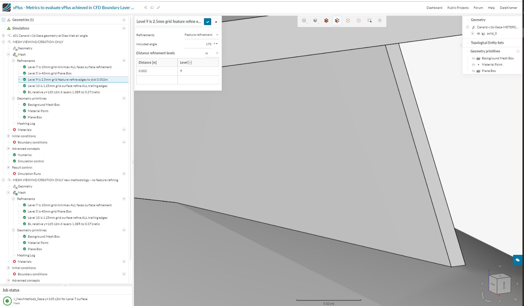
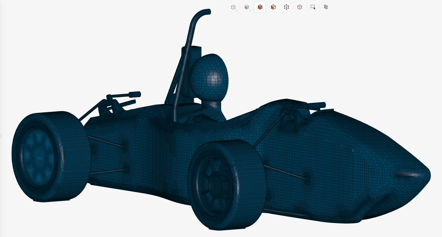
I think it would help you now to have a look at and analyze my one of my better geometry files from last year and this mesh of it … (some of my current methods may not be present in it)
EDIT, darn, I see I used my dreaded ‘feature refinement’ a little bit there (I remember the headaches now back then ,ugh), I should redo that with the method I tell you here, that would be interesting…
Doesn’t hurt for you to look, there are many ways to skin a cat, I will try to find a current mesh that matches my recommendations in this topic, like I said I need to get my current approach ‘onto paper’ , but I will do that tommorrow…
EDIT, the next morning So I did go back and try to see if I could get as good a mesh WITHOUT that ‘feature refinement’ I had used and sadly I did not get a better mesh… (maybe with a little more effort I could have)
This VERY SPECIFIC settings ‘feature refinement’ was needed there in order to keep the trailing edges defined in one small location at the top rear of the fuselage… (I still don’t know why a very fine 0.625mm surface refinement did not work on the trailing edge at that 2.5mm wide spot)
I would keep this as an edit post by the way and create a completely new one where only the author makes edits and (optimally) no comments are added. The visitor wants to read through the post without having to jump through arguments, so that’s the way I prefer to do it.
Let me know what you think and if you need any specific help! Dale will also run the study for the cell centroid issue we discussed in another thread.
Yes that is a very good idea. Then it could be more of a solutions guide then a back and forth. Reading other threads this was definitely time consuming and confusing sometimes jumping all over. Maybe it would be best to wait until all the topics i wanted to cover are solved, with documented evidence, then i can upload a final “solution” for everything.
But then how are you going to ask questions along that journey, please continue here if you have questions…
Maybe you will become a PowerUser and your first job could be to succinctly summarize a successful meshing and layering journey
I think what he meant was to summarize / show the main points of this conversation in a new thread and to make it strictly an instructional guide so that everything is easy to access, as you said, in a linear way. This thread should definitely be the main source, so dont worry everything will be here until it is time to make that new thread.
Haha thats a bit optimistic. The main reason for working toward mesh accuracy is because im doing my masters thesis and i wanted precise CFD results. This is just one part of the project but i wanted to get this right as i know a lot of beginners to CFD (i would include myself in this category) dont really know how accurate the result are as creating the correct mesh is an extremely important part of correct results.
Therefore, this is my favorite quote haha
P.S. Maybe I wont be a power user but I will be looking for a job after my thesis is done
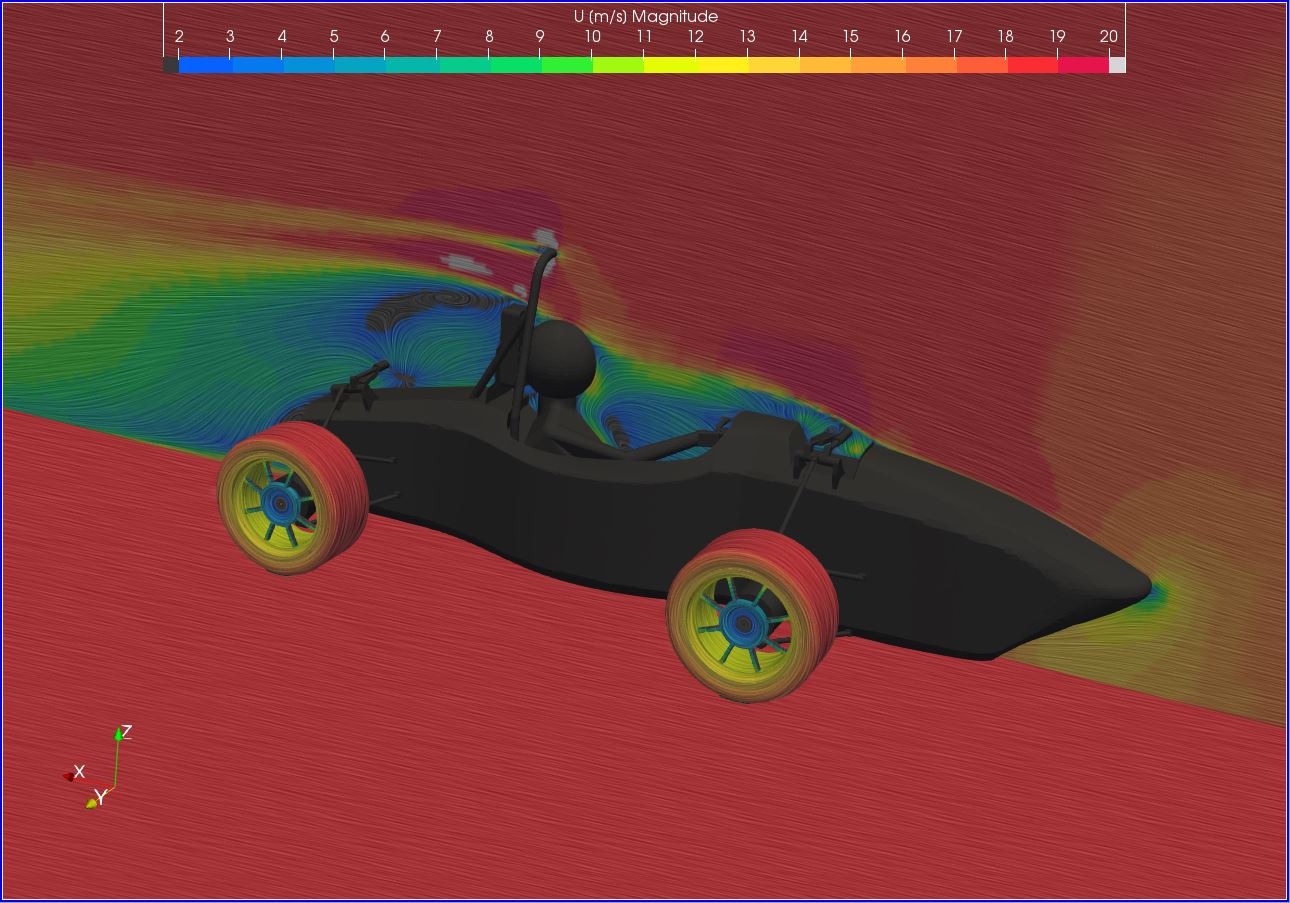
Since you asked, here is the Y+ mapping for the boundary layer conditions with the settings:
Layers: 3
Expansion Ratio: 1.3
Min thickness: 0.001
Final Layer thickness: 0.3 Same settings as above for boundary box layer addition
since we already discussed that the relative cell size option effects the boundary layer refinement cell size because of the ratio between neighboring cells. It is important to add the surface refinement sizes i used, as well as the overall cell sizes. Here is this information:
Based on boundary box cell size I calculated
Calculated X direction
18-(-9.825)105 = 27.825115 = 0.2419m
Y and Z direction
7.201 - 0.00130 = 7.230 = 0.24m cell size in the Y and Z direction
Level 0 (calculated)
0.24m
Level 1
0.12m
Level 2
0.06m
Level 3
0.026m
Level 4
0.015m
Level 5
0.0075m
Level 6
0.00375m
Level 7
0.001875m
Level 8
0.0009475m
Level 9
0.00046875m
Level 10
0.000234375m
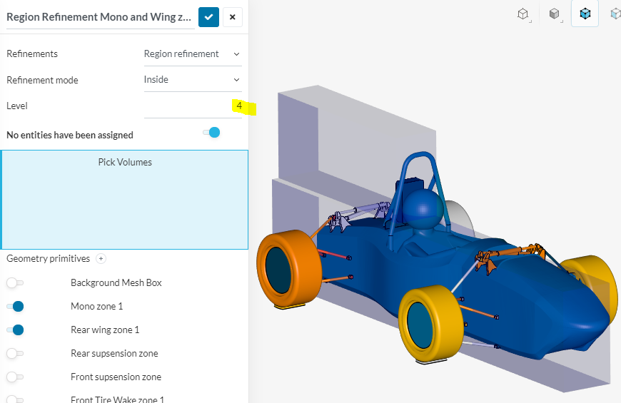
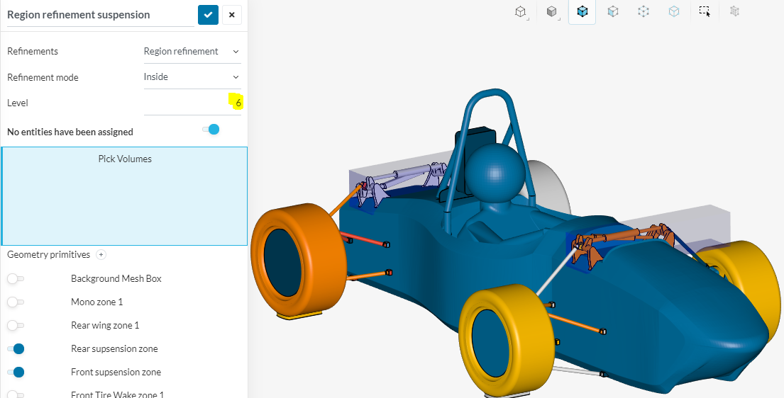
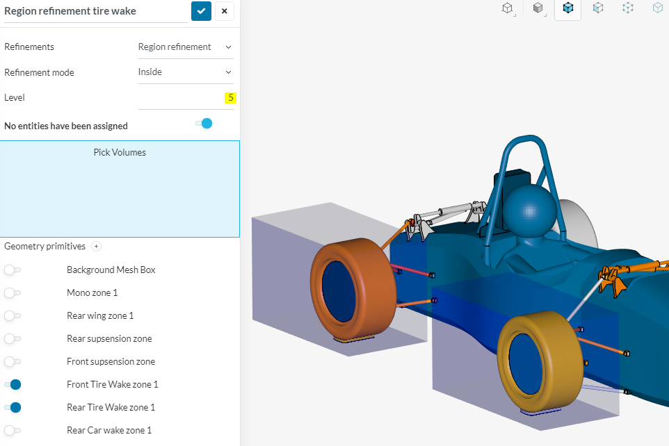
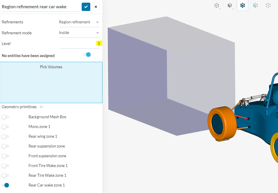
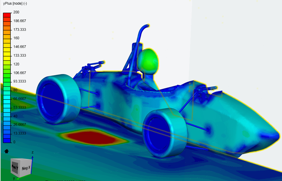
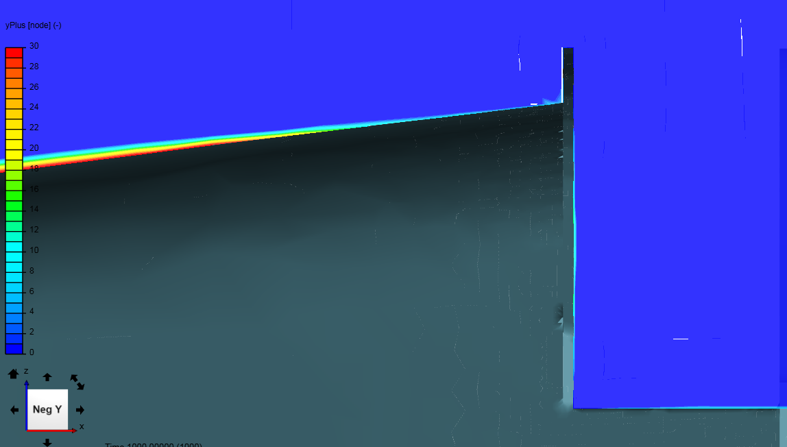
For this simulation i tried a method of multiple region refinements so that different levels could be used to reduce overall cell count. I think now looking back on what i have learned this is probably not the best method as the changing levels also change the Boundary Layer sizing (again due to the relative cell sizing). This is shown later in the drastic changes in Y+ on the model.
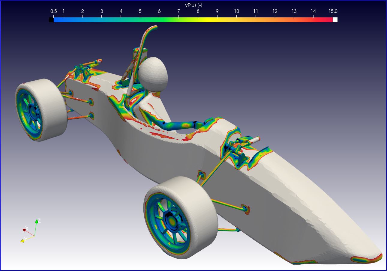
Y+ Mapping with scale from 0 - 200 - notice the red patch between the wheels. This is definitely due to the lack of a region refinement between the wheel wake zones. This creates a region where the boundary layer refinement is measured relative to the level 0, wind tunnel standard cell size, and thickens the boundary layer out of the desired Y = 30 zone.
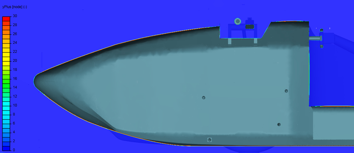
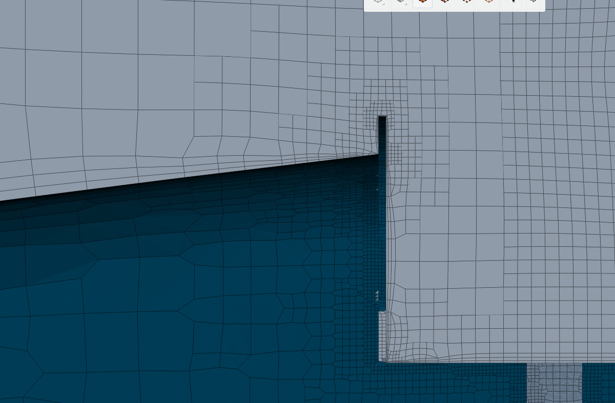
Zoomed in section showing how the relative boundary layer option becomes smaller (as seen in the mesh cells). This result is not ideal as you can see the virtually non-existent boundary layer behind the foot pedal cover
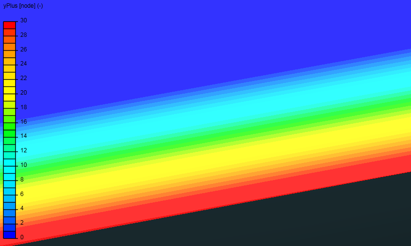
Last but not least, a full zoom of the Boundary layer of a section near the main area of the mono. This boundary layer size should be in relation to a mono surface refinement of level 4 = 0.015m and a region refinement also at level 4.
This is where I am starting to get confused as how these calculations work and which cells are related in this ratio.
Based on what you said here:
So if i am not wrong in my calculations, we have a first cell size of 0.177m (not calculated by me). with an expansion ration of 1.3 the final layer thickness of 0.3 should be the ratio between the first cell size of the boundary layer (the one that was calculated) and the surface refinement to be chosen ( in my case it was level 4 at 0.015m because i didnt know this is how its supposed to work)
Boundary layer settings - Layer calculation
Layers 3
1st 0.177m
2nd 0.23m
3rd 0.3m
Expansion ratio 1.3
Min thickness 0.001m Final layer thickness 0.3m with relative sizing this is the RATIO between the first boundary layer cell size (if this is correct), which is calculated at 0.177m and what the surface refinement cell size should be which gives us:
0.177 X 0.3 = 0.0531
Based on this calculation the cell surface refinement on the mono should have been around level 2 (0.06) or 3 (0.026) to give an accurate 0.3 ratio between surface and boundary layer. And this ratio is important so that there is not such a large jump between cell sizes giving accurate results, am i correct?
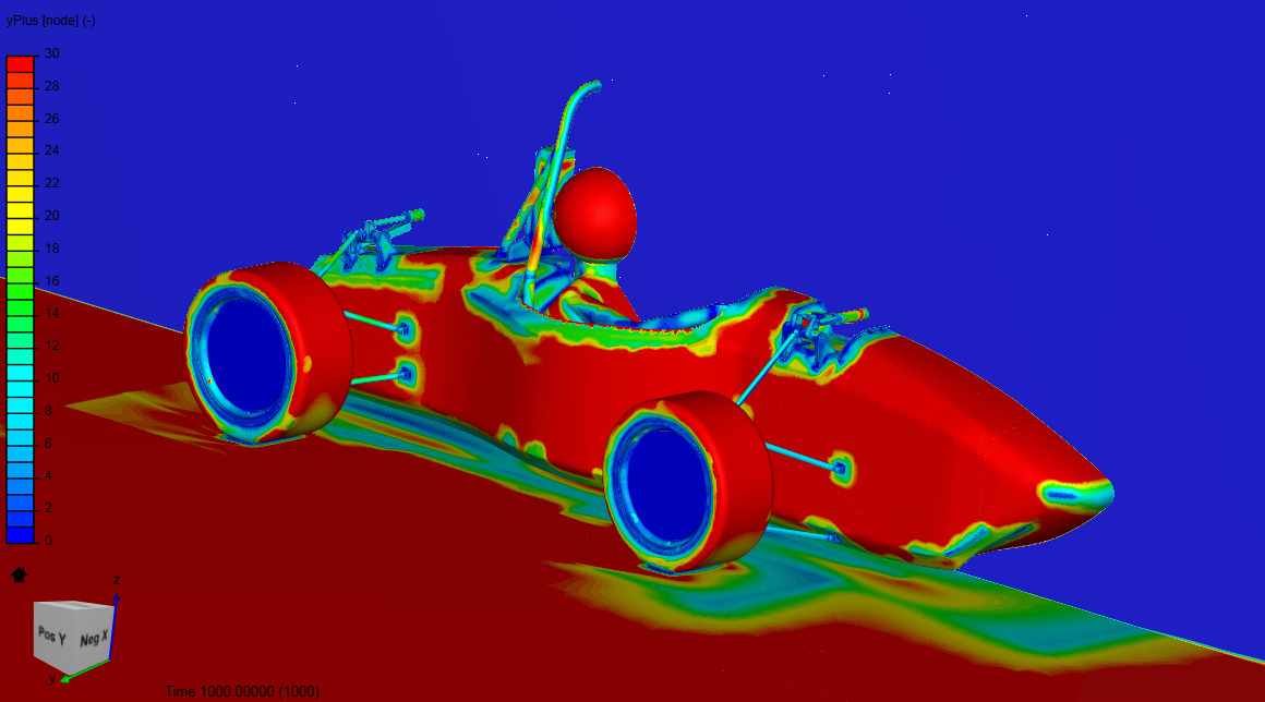
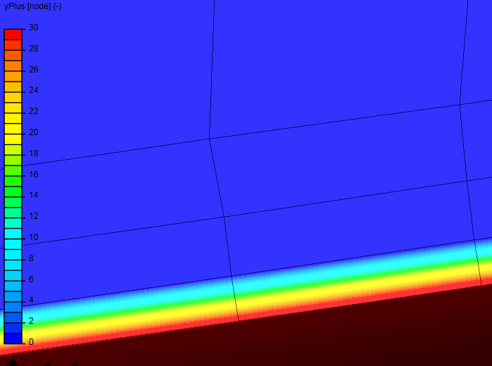
I am aware that the above calculations are completely incorrect for my goal as shown by the picture below where my first cell size is much to large for the red Y+ = 30 region.
yPlus only has non-zero values on the geometry surface, (that rainbow you see in the 1st layer in your LASTimage is just a PP ‘mirage’ of how they think yPus goes from a non zero value at the geometry surface to 0 anywhere off the surface, there is for instance, NOT a yPlus value of 16 somewhere in the 1st layer )… I will go deeper into that, a little later.
I the meantime can you give me a direct link to the sim run for all the y+ images you have posted?
That way I can show you the way I look at a yPlus mapping and more…
I do not see the any EqualMaxMin surfaces that will be used for the 0.3 FLT ratio calculation to give you the first layer thickness that your y+ calculator has determined for you (1st layer thickness = 2 times cell centroid distance for some y+ calculators)…
Please show an image of your filled in y+ calculator for that sim run link that I asked for above…
I would expect to see WIDE variations in y+ over all those surfaces… unless you layer them individually with their own ratio. Which is likely what you should do since some of those surface groups are quite flat and some are very detailed).
I assume you are adding layers to all those surfaces… until I see that sim run for those y+ maps, I can’t help much more…
Your level0 cell size of about 0.24m is likely going to come back to haunt you as too fine when you want to optimize your BMB size in meters… I use exactly level0 1m for my cars and airplanes, which allows larger BMBs without big increase in number of cells for larger BMBs.
Yes this whole sim was done from the last mesh i did (No Aero 1.1 - Mesh QT 4) where the boundary layer was the same settings as the Bounding box layer addition settings provided by the FSAE Tutorial. I have not yet done a mesh or sim with correct values or methods you described (the equal min max method) i wanted to see these results first then understand that my calculation method of the final thickness ration to surface cell size was right.
i can increase the level 0 cell size on the next mesh. that would help a bit with overall cell count but my current wind tunnel size is 28m long so a 1m cell size might be a bit big, but i trust your input. Reducing the cell size isnt really a problem so i will try it.
So the next mesh i will do will be based on the following plan:
determine Y+ cell size, you suggested using 50 so i will do that.
use a level 0 background box cell size of 1m
Determine which level will match the necessary cell ratio between the surface refinement and first layer size.
apply an equal min max surface refinement to all surfaces at level determined in step 3.
apply any necessary unequal min max surface refinements to small face areas that require it.
any advice on region refinement size? i would assume as close to the final layer cell size thickness as possible but im not sure.
So using my plan above this results in the following:
Desired Level 0 cell size = 1m
Level 0 (calculated)
1m
Level 1
0.5m
Level 2
0.25m
Level 3
0.125m
Level 4
0.0625m
Level 5
0.03125m
Level 6
0.015625m
Level 7
0.0078125m
Level 8
0.00390625m
Level 9
0.001953125m
Level 10
0.0009765625m
Y+= 50 used for 1st cell thickness size
Expansion ratio - used as suggested - 1.4
Final thickness (RATIO) - used as optimal starting point for further calculations. - 0.4
Layers
3
1st - Calculated
0.00108513m
2nd
0.001519182m
3rd
0.0021268548m
Overall thickness
0.0047311668m
Expansion ratio
1.4
Min thickness
0.001m
Final layer thickness (RATIO)
0.4
0.4 would be the optimal ratio as the input for final layer thickness, so this is our goal. Based on this the following calculations are made.
0.0021268548m = calculated 3rd layer size in boundary layer creation (see table above)
X = the exact layer size we need to use for our surface refinement level
0.4 = our optimal final layer thickness ratio. (we are using this temporarily)
0.0021268548m / X = 0.4
0.0021268548m = 0.4 X
0.0021268548m/0.4 = X
X = 0.00542137m
This number is what we will use to select the closest level for the surface refinement level
Closest levels from bounding box calculation ( shown in first table)
Level 7 at 0.0078125m
or level 8 at 0.00390625m
0.0021268548m / Level 7 (0.0078125m) = final layer thickness ratio = 0.272
0.0021268548m / Level 8 (0.00390625m) = final layer thickness ratio = 0.544
Therefore Level 8 give us a ratio of 0.544 which is closest to our desired 0.4 ratio. The only way to make the ratio between these two cell sizes an exact 0.4 or to make it any ratio that you need, The base level 0 cell size must be changed so that the calculated level creates a perfect 0.4 ratio.
Dale, i now know what you meant
While the ratio is not at 0.4, and i know it must not be exaclty 0.4 but i assueme a range of 0.3-0.5 is optimal, i should rework my level sizes so that it is close to 0.4.
Just making a mesh is definitely more work then i thought. I should say an “accurate and correct” mesh is a lot of work
EDIT based on the optimal 0.4 ratio i calculated the correct level size shown below.
For level 7 calculation of level 0 cell size
X/128 = 0.00542137m
X =128 * 0.00542137m
X = 0.6939
Level 0 (calculated)
0.6939m
Level 1
0.3469m
Level 2
0.1734m
Level 3
0.0867m
Level 4
0.0433m
Level 5
0.0199m
Level 6
0.01084m
Level 7
0.00542137m
Level 8
0.0024972m
Level 9
0.0013552m
Level 10
0.00062431m
Now i must return to the bounding box cell number and size to make sure that the level 0 cell size of 0.6393 is created in the X, Y, and Z directions.
Based on our level 0 cell size of 0.6939
To get an approximation for how many cells are needed for our bounding box size (the bounding box size will change slightly later but i do not want to drastically alter the size) we will do the following calculations.
I know the calculator links, I just want to see an image of all the values you used in them when the layering parameters for the 6383751 cell mesh was generated. that is the only way I can figure out your y+ issues…
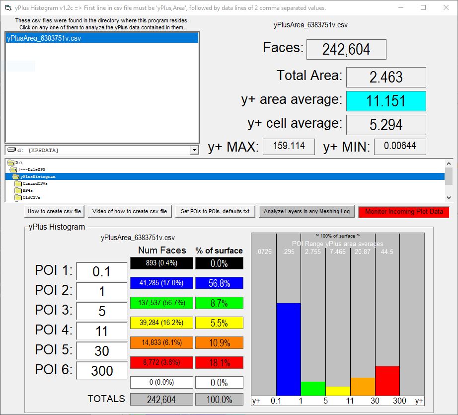
For instance on this sim run , here is a y+ surface mapping (using combinations of my methods described so far you could get your whole surface to be >15 y+ where wall function BC is best used):
One of us has to figure why the road surface has velocity greater than 0 mps. If it were a no slip wall, it should be 0 I think…
1st off, I will definitely suggest doing the car body for y+50 at a 0.4 ratio and all the small items may not even need layering, but if you decide to, do them at y+50 using in a different layering refinement with finer EqualMaxMin level at a 0.4 ratio.
I have not even determined myself if the tires need layering…
Decisions like the above two, can really only be answered by running with and without a layered mesh in those areas, to see the difference in force or coefficients results… If very little difference then don’t waste time layering them now or in future cars of similar design…
 )… I will go deeper into that, a little later.