I am a hobbyist, and new to this level of CAD and simulation. Modelling an object suspended by 3 to 6 flexible cables (inextensible for modelling purposes) is causing me much thinking and not much action. I am looking for tensions in cables (or chains or strings), plus ability of object to withstand small forces at right angles to gravitational field. I was trying to figure out how to parameterise suspension attachment points (say relative to centre of mass), amongst other issues. I couldn’t find anything vaguely related, so if anyone can give me a lead for something to look at and learn from, please comment.
Am I correct that to model an attachment point that can move at any angle, that I need to insert a small piece so can have two rotational surfaces at right angles? Or is there a better way?
Hi @rigtig! First of all a warm welcome from SimScale. You registered not that long ago 
Interesting application you are dealing with. May I ask if there is already a model set up by you that you have uploaded on our platform? If so, please let me first have a look at it and let me think about some strategies that we can use in order to make some first approximations for this type of simulation.
Looking forward to see what we can achieve here 
Cheers and all the best!
Jousef
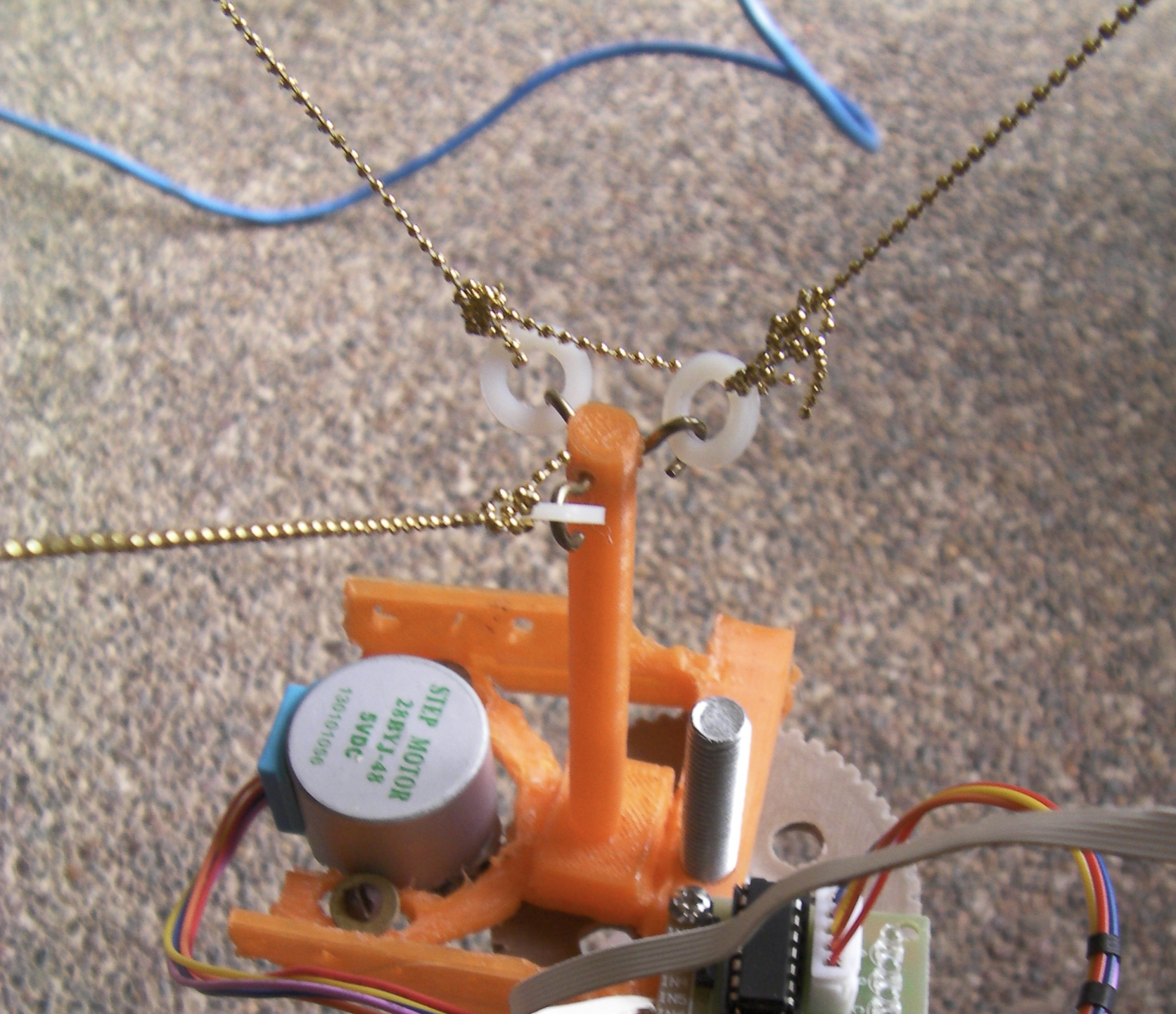
I had my first go at using FreeCAD and I have loaded it into. For more background, see RigTig's Big 3D Printer | Hackaday.io. In particular, the comment about wobbling of the effector (Wobbling of effector | Details | Hackaday.io) which is what has led me to experiment with simulation.
It is all fun to learn more every time I have a go a something. I certainly run out of day before I run out of things I am working on!! And I am supposed to be retired!!!
I put up another model (SimScale) and I have played around with various options and scenarios. I’ve decided that, for simplest simulation, the strings and attachment points are irrelevant to actually simulating the stability of the core object (which I call the effector). The simplest way to simulate the strings is to have a fixed object upon which each support surface rests. If there is any rotation of the effector away from vertical, then it just lifts off one or more of the supports, which is equivalent to a string becoming slack.
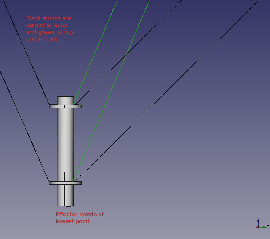
I also put a pointy tip on the effector, and it is this tip which is the key reference point for the measure of stability - since it is where material is extruded by the effector. A more sophisticated simulation needs to constrain each support point to be on the surface of a sphere centred at the remote end of each string, or (when a string is slack) inside that same sphere. I am not sure how to do that yet, but if anyone has an idea, please comment.
Hi @rigtig!
Regarding the extruder support: How does the full model look like? It seems that there are missing parts inside the CAD model you uploaded. Can you upload it as a STEP file please. It is consisting of shells now.
Had a look at the webpage. That is such a cool project you are doing here!! I am impressed tbh. ![]()
Yet, there are some questions I have as I am not 100% sure about the effector model.
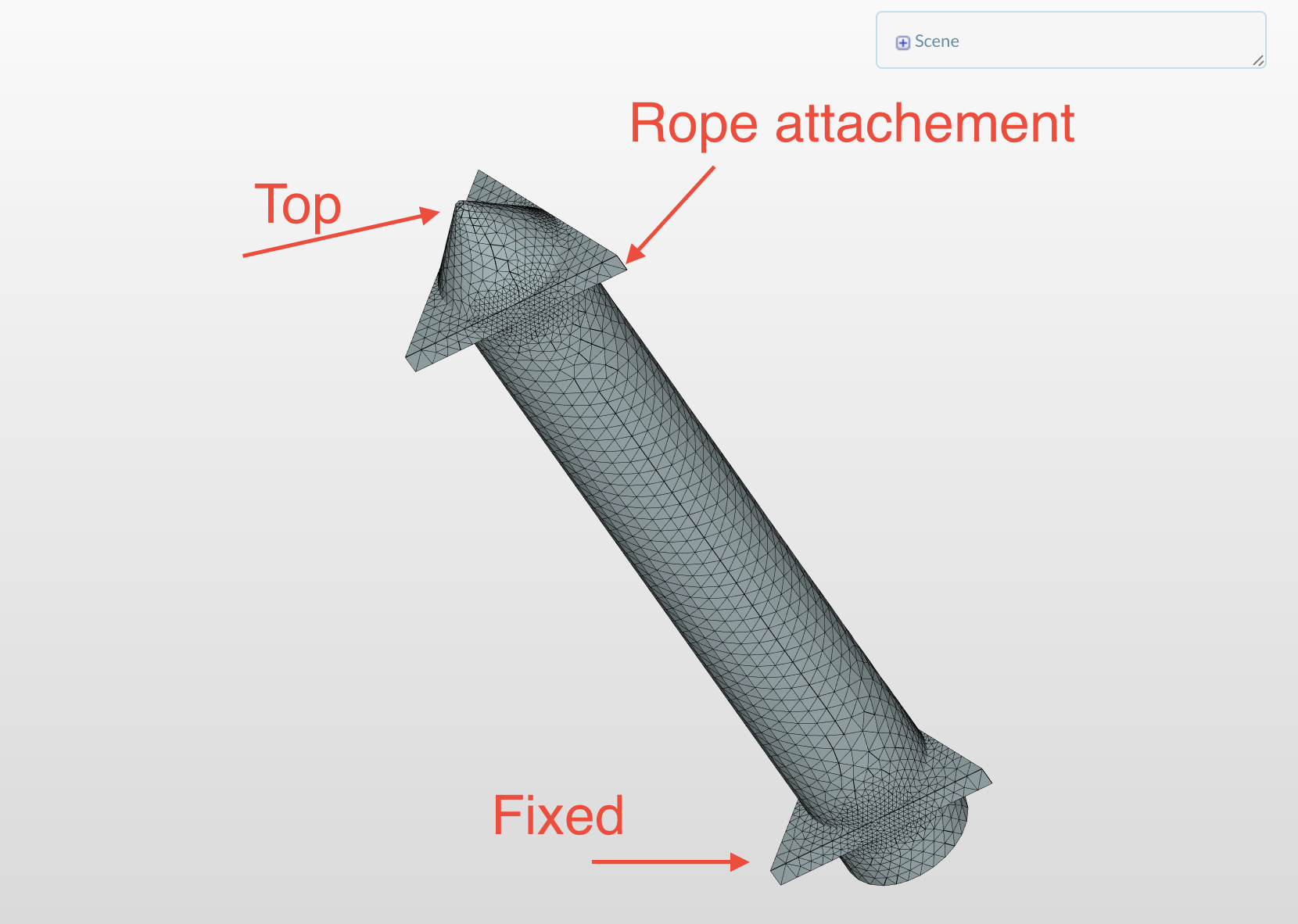
Do you want the Bfs as depicted in the picture or did I get you wrong here? Would be nice if you could do something like a small “sketch” if that is okay for you as I could not fully grasp the concept/function of your CAD model. Is the rope attachment (if my sketch is right) the top of your real model where the chains are attached?
I am also tagging my colleague @rszoeke here. I am sure he has some good impetus for your project. Especially when it comes to boundary conditions and the physical limits we have to take into account as I am not sure if we actually are able to simulate ropes/chains (sure, to a certain extend with some simplifications).
Cheers!
Jousef
Aha!! Yes, a bit of explanation might make things clearer for you. Think of an effector to be something like a glue gun: you put some solid stuff in one end, melt it and squeeze the glue out a hole in the tip. An equivalent can be the cartridges used by builders to apply silicone sealants, but they don’t use heat. The reason for calling it an effector is that it is exactly the same as the cutting bit on a CNC machine or a tip on a plasma cutter.
The most common way of moving the effector about in 3D space in a 3D printer is to fix the orientation of the effector to be vertical and use motors acting parallel to each of the cartesian axes to position the tip just where it is needed. This leads to building up the 3D object in layers, with each layer being a series of (non-zero-width) lines, just so the effector does not run into prior build material.
Another way of moving the effector around is to have a plate supported from three ‘points’ using extensible rods, with each support being two rods acting as a parallelogram for stability and to control the orientation of the effector. This style is called a ‘delta’ printer.
Anyway, my idea came from seeing a design for a drawing machine with strings supporting a pen horizontally so it drew on a (nearly) vertical surface. In this design the motors were in the top corners of the board. Well, if 2 motors gives a 2D picture, then 3 motors gives a 3D picture. At this point, it became obvious to me that the size of the printer could be anything from a desktop to a football stadium. And, cameras flown about stadia on wires (just thick strings really!!) are common. Gee, it cannot be too hard can it?
Several years later, I can say that I have had a continuous education from this project. Yes, my prototype worked - at about a cubic metre, though the reproducibility was questionable. It is when I went to room-sized that the wiring became a real problem - and that has taken the bulk of my focus for the last couple of years. Now, I am back to the stability of the effector - because it just swings about in 3D space.
Effectively, the point of intersection of the extension of the 3 strings is well-defined, but depending on just gravity to constrain the orientation of the effector to be vertical is, well, idealistic. Making the centre of gravity of the effector further below the effective support point does increase the moments to keep the effector vertical - but only when it is not moving. Add in the inertial effect of actually moving the effector around just makes for a disastrous 3D print, further complicated by the surface tension of whatever is being extruded dragging on the tip. Mmm…time to do something to better understand the effects and what can be done to mitigate the ‘wobbles’.
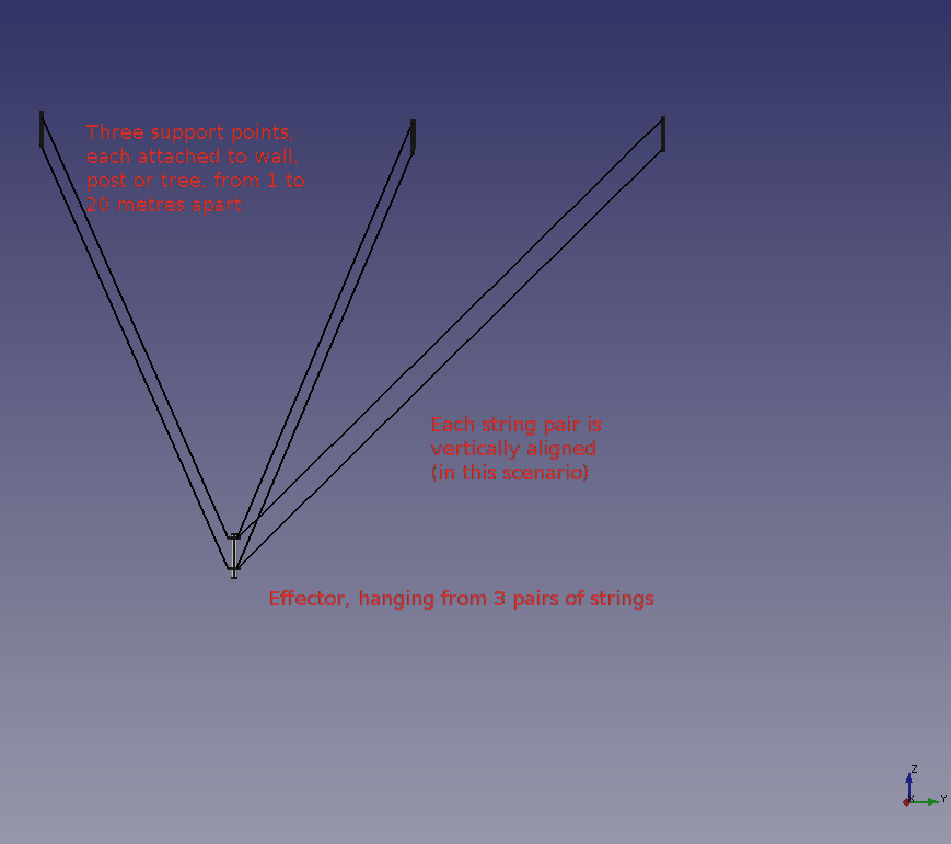
So, I decided that having two strings from each support might be the way to go. My intuition said to have the attachment points vertically positioned, in contrast to the layout used for delta printers (horizontal). But others have suggested otherwise. And what should the relationship be between attachment points and centre of gravity? And…
So begins my learning about simulation and a myriad of new terms - like FEA. Somehow, I found a link to https://www.simscale.com (maybe from another project on hackaday.io, but I cannot remember). I register, and then discover that I need to create a model offline. Well, I’ve used OpenSCAD to create STL files to 3D print, so how hard can it be to find something to produce STEP files? Constraints = for free, and I use Linux. So, I have a go a FreeCAD, but it took me a while to discover the button to make something that looks solid to actually be solid. In my defence, note that OpenSCAD is a solid modeller so coming to terms with a surface modeller has been another learning experience (and obviously, still underway).
Whew. I hope this background assists with your understanding of this problem space. Many thanks for all assistance. Even Vincent gave me some hints via chat last night - thank you.
Here’s a couple of annotated diagrams to assist understanding:
Hi @jousefm,
I got a couple of successful simulations! The first one was just 3 remote displacement boundary conditions, effectively simulating stationary effector hanging from 3 strings (see SimScale run 6). I then applied a 0.01N force (about 1gram) to a vertical face well below the suspension centre and centre of gravity, and got a ridiculous displacement of 10,000 metres! Well, I think that is what it means (see run 9). The fact that I got anything to run at all is a minor miracle as far as I’m concerned. Now, I’ve just got to learn a bit more about what I am doing and how to interpret the results.
Hi @jousefm,
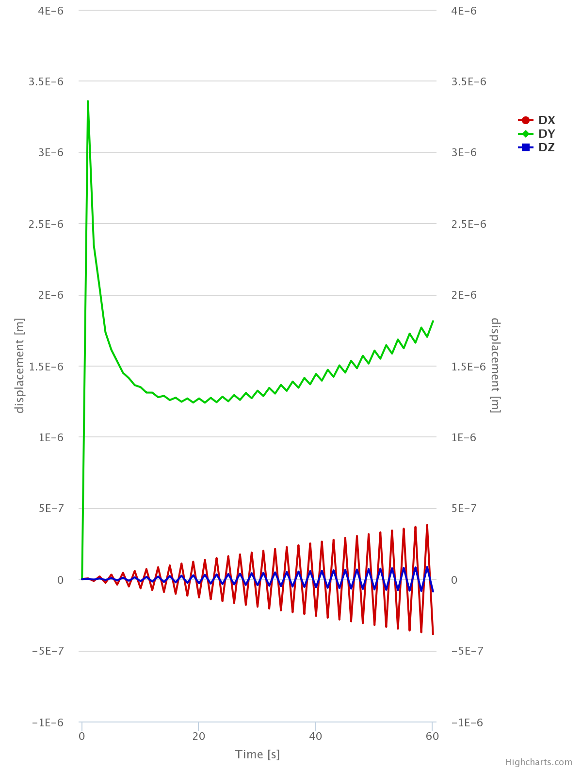
I’ve been playing with various settings. My latest simulation is run13 in simulation ‘hanging’ where I have 60 seconds at 1 second intervals for the extruder just hanging from 3 strings, but moving at 100mm per sec. As I expected, it is unstable, as shown (for example) by plotting the displacement of a point at the tip:
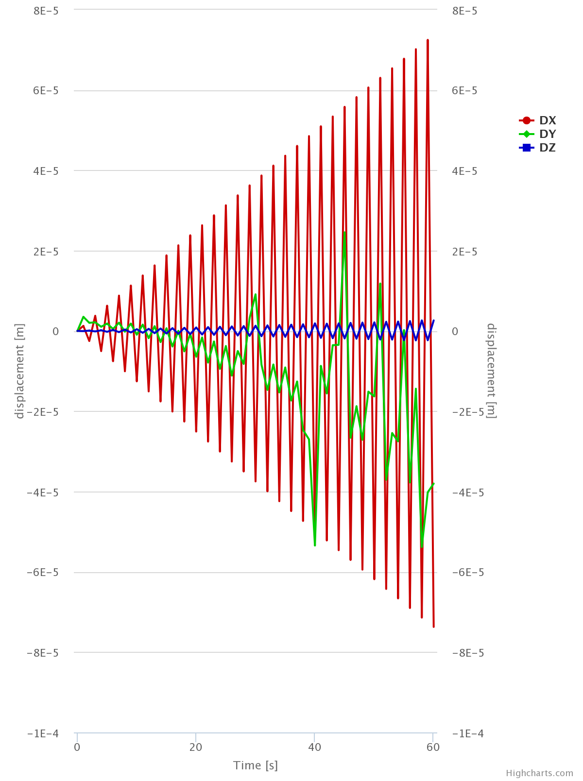
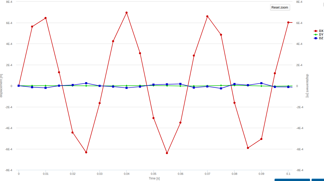
OK, having finally got a bit of a handle on using SimScale, lets try a few changes to the model to see about stopping the ‘wobbles’. Firstly, adding three more strings changed outcome to:
Note that displacement is much smaller, but not sure about the biggest movement in y axis when movement is in x axis…something for me to check out there.
@anon18194957, It might have taken me a few days to start to understand how to use SimScale, but that is a lot shorter time than building real stuff and trying it out. Making modifications is just so much easier in simulation that it is crazy to even think of doing this evaluation using real stuff. I am not sure that it would even be practical to measure some of what can be simulated. Thanks for your encouragement.
Hey @rigtig,
Love how fast you grasped the concept of the platform and already did some good simulations autonomously
Let us know how things go!
Cheers!
Jousef
Hi @jousefm,
The more I try, the better I understand. I’ve found that setting the time increments manually gave me results that didn’t match my expectations, but that allowing automatic time increments really did show the instability I had noticed in my very limited real experiments. The best example is in RB3DP stability - hexagonal by rigtig | SimScale under Simulation ‘3-string dynamic’, run ‘4 vi.1’, where the tip oscillates about ± 0.5mm caused by 100mm/sec velocity only.
The forces on each of the support areas is also calculated, which is really useful for final design of strings and drivers. There’s something on SimScale site about ‘pretty pictures’, and it is really important to look carefully at what the pictures say to determine what you learn from them. For example, the displacement graphs above implied that the oscillation just keeps getting bigger (over 60 seconds anyway), and that just did not seem sensible (at least in this scenario). So, that’s when I tried other options in analysing this situation. It is indeed unfortunate for me that none of the other dynamic analysis tools (modal, frequency and harmonic) accept the remote displacement boundary condition, so I might need to come up with another physical arrangement to simulate the strings support.
Anyway, this is just a bit of an update for you. Whilst poking around the SimScale site, I found Milad Mafi’s workshop on the extruder for 3D printer - which is very relevant to my overall project. I am not sure how to reach out to him, but if you think that he might like to see what I am doing, please can you point him to both my SimScale work and stuff on hackaday.io.
Thank you for your interest.
Hi @rigtig!
Seems that you are on a SimScale rampage! Will definitely have a look at that later on!
Already reached out to @anon67859130 and told him about your exciting project. Maybe he will add his own comments on that soon 
Cheers and keep those simulations coming!
Jousef
Hey,
Great job!
This would a perfect example for our next 3D printer related workshop!
Cheers,
Milad
Hi @rigtig,
nice progress so far! I see two main regions of improvement in your setup.
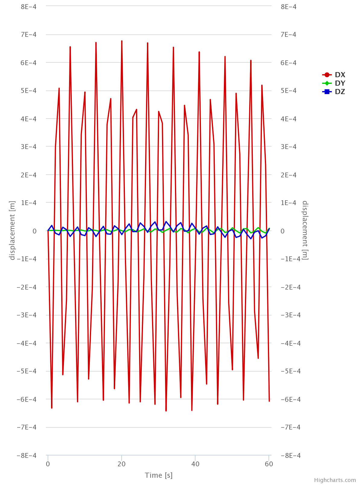
First, the time step size (1 second) is much too high - this would be ok if you want to resolve pendulum frequencies of about 0.1 Hz and less. You can see hints towards this by the “zig-zag” displacement curve and that the “displacements seem to keep getting bigger”, as you noticed. I copied your project and did different runs with varying increment size - with very drastic result changes:
Time increment 20ms
Time increment 5ms
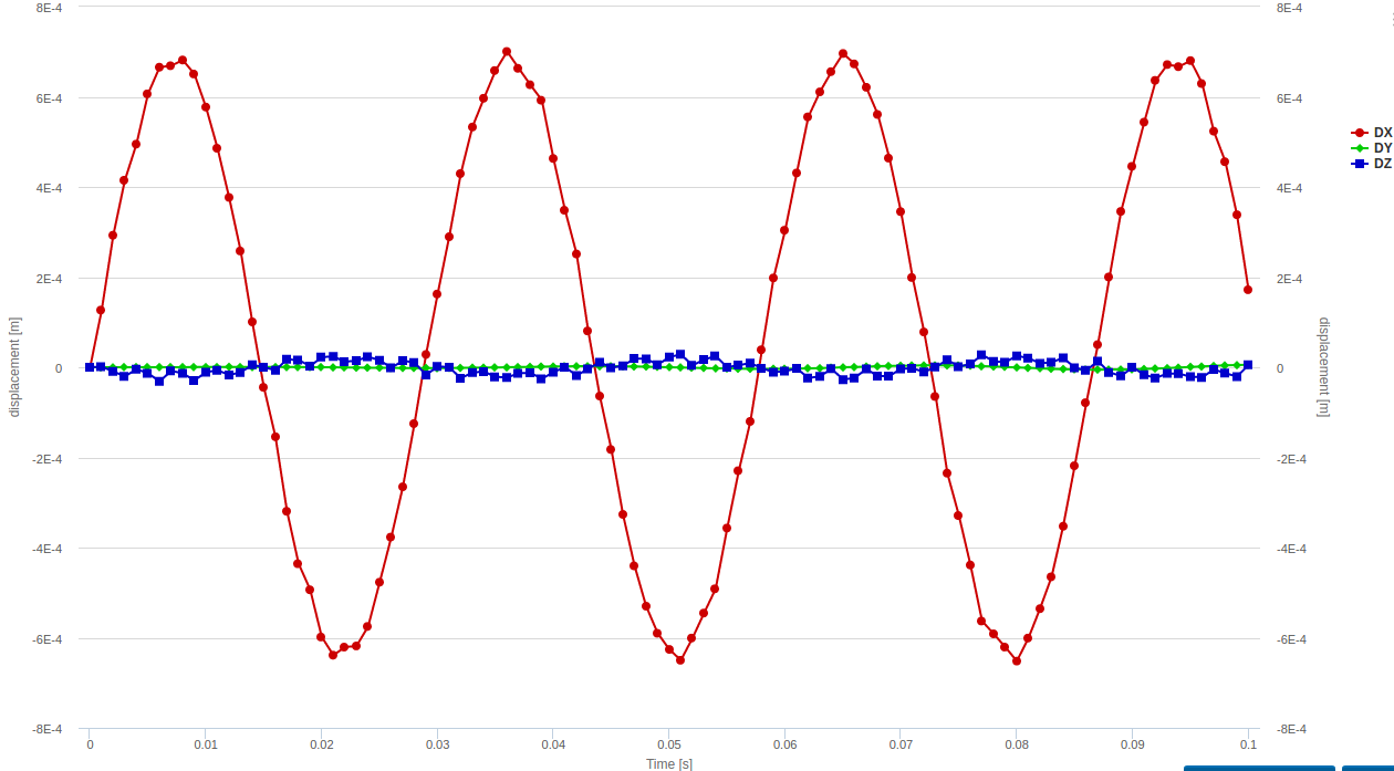
Time increment 1ms
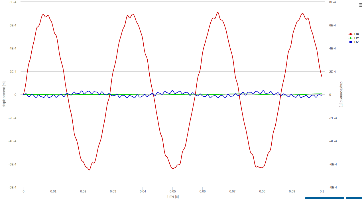
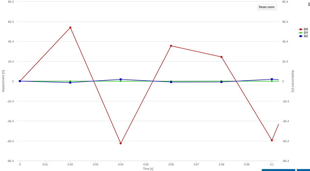
Time increment 0.25ms
You judge which step size would be acceptable.
You can check out the project here.
Your approach is very interesting and could be valid to some extend - modeling the moment-free mounting by the strings. What this approach fails to model is the basically zero compression stiffness of the strings. So I would expect that the actual freuquencies which you observe are lower than the ones in this model. But I guess this is as close as you can get with the capabilities that are currently available.
Best,
Richard
Thank you very much Richard (@rszoeke) for extra analysis. It is not something that I has thought of, but it shows the harmonics very clearly. In the 0.25ms steps analysis, the most important thing I’ve learnt is the maximum support force (over 15N) needed for an object weighing just ~180g. The fact that there are harmonics is also relevant, but the frequency is not critical at this point in design process. This extruder body is a very simplified approximation, I viewed the extruder from +y over all 400 steps and it is fascinating to note tht the pivot point is not stable at all.
I am not at all sure what I can do about the extruder flexing oscillations, or indeed if I’ll need to. SimScale does not provide any insight into the tip movement relative to a ground-based reference, but I am sure it is much bigger than the <0.2mm caused by object (extruder model) flexing.
An alternative model to allow for zero compressibility of string support might be to have the extruder rest under the support points upon another body, which is, in turn, constrained to be fixed to the ground. Any rotation of the extruder away from vertical lifts at least one support off so there cannot be any support force at all. Now making sure it does not slide off might be an interesting challenge! Not worth following up for me at this time, but I might come back and have a go, just to see how it models.
My first couple of weeks doing SimScale analysis has been very interesting and informative. I really had no idea what what possible, and I have been pleasantly surprised.
Milad (@anon67859130), I am not sure it is mainstream for 3D printers, but this is something just a bit different for people to think about. I’ll certainly be doing some simulation work on heat flow in extruders, but not just yet. Of course, you are welcome to use and modify whatever I have been able to cobble together so far.
Hi @rigtig,
I just noticed that for your force calculation you used “min/max” instead of “sum”. I added a new run to the project mentioned above with corrected force calculations. The max total force in vertical direction is now about 35N.
Best,
Richard
@rszoeke Please can you remove some confusion in my understanding of the SimScale force calculations. I’ve had a look at SimScale doco, and not found anything to clarify about using “min/max” or “sum”. So maybe, there is an opportunity here to also help another newbie and get the doco updated. What is the sum of?
- I assumed the sum was over time, and that is not what I want. I had chosen “min/max” because I am aware that the modeling of the string support is inaccurate (since a string has no compressive strength to speak of), and I wanted to know how much upward force was in the model.
- Is the force reported by SimScale on the whole area selected? For example, ‘force1’ is on ‘faceGroupOnGeoFaces_16’. It is only one face anyway. so summing doesn’t make any sense to me in this scenario, and yet the reported force increased over 200%.
Next question: How real is this simulation? Is the maximum tension in the real string going to be really as high as calculated here? It seems to me that an object of about 180-190 grams has got some really powerful leverage to exert a force of 35N in vertical direction.
TIA, RigTig
Hi @rigtig,
let’s try to answer all your questions one by one.
I’ve had a look at SimScale doco, and not found anything to clarify about using “min/max” or “sum”. So maybe, there is an opportunity here to also help another newbie and get the doco updated. What is the sum of?
Regarding the result control items for “min/max”, “sum” and “average”, the relevant documentation link is this one. SimScale Documentation | Online Simulation Software | SimScale You should find all answers there. If not I am happy to resolve any remaining doubts.
- Is the force reported by SimScale on the whole area selected? For example, ‘force1’ is on ‘faceGroupOnGeoFaces_16’. It is only one face anyway. so summing doesn’t make any sense to me in this scenario, and yet the reported force increased over 200%.
The force “sum” is calculated by summing the force values of all nodes that belong to the assigned faces. Summing is done w.r.t. single nodes, so the actual number of faces is irrelevant, only the total number of nodes they represent.
Next question: How real is this simulation? Is the maximum tension in the real string going to be really as high as calculated here? It seems to me that an object of about 180-190 grams has got some really powerful leverage to exert a force of 35N in vertical direction.
I am not sure that I can quantify how much your calculation is off. The problem is that in addition to just the weight (by adding gravity), you also have an initial velocity (0.1m/s). This does not sound like a lot, but you are dealing with a model where you replaced “strings” with a remote load that acts on this long distance between remote point and connected faces as a rigid bar with moment-free with a hinged connection to the part. As your part itself is relatively stiff, the initial velocity is decelerated within a very short distance (which is the deformation within the part relative to the hinge points). The stiffer your part, the higher the force - which is not really what you will have in reality, since there the stiffness of the cables is the relevant factor as the deformation for a long cable will be much higher than the deformation on your part.
What you would need is a model where you add an additional 2-part component (similar like a damper) which in tension has the same stiffness characteristics as your cables and in compression detaches by using a physical contact between the parts.
To me this sounds like a lot of effort to get this model working, but if you want to try, I would certainly try to help you.
Or maybe someone else has a better idea?
Best,
Richard
@rszoeke, many thanks for link. It didn’t come up when I went looking. So, navigation around the help may need some attention. Ooohh!!, and have to read it carefully to realise that whilst there is no way to specify a force at a node that the calculations give forces at nodes. A bit tricky for a novice to get their head around, so thank you for the heads up.
I’ve learnt heaps from just my first foray into any kind of engineering model analysis. F=ma, and if you make ‘a’ big enough then the ‘m’ can still be quite small and get a big force. So, yes, this exercise has shown me that understanding the approximations and simplifications is really important to getting a meaningful result. I think I’ll leave any further modeling of this for the time being. So, thank you for your offer to assist with further refinement, but I think I’ll just leave it as ‘an exercise for the reader’. So, if anyone else has a go, please comment in here to allow me, and others, to follow through.