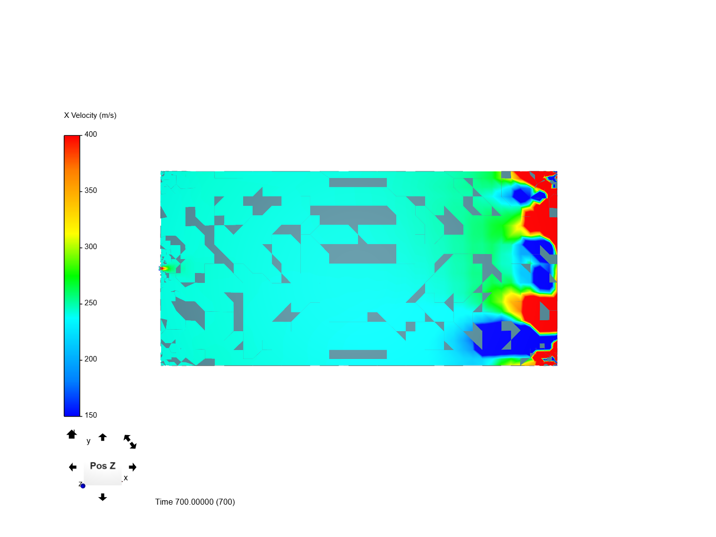
My problem is that when I post-process my results I see that the outlet boundary condition is not respected (considering the velocity).
I think that my bc are a bit messy but I don’t precisely know what is wrong.
(In addition: can you please confirm me that I’m using a correct turbolence model? The flow outside the nozzle is more steady than I expected)
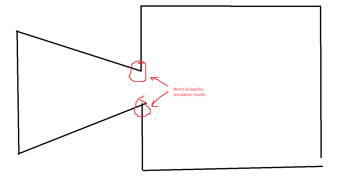
If you want to use “Nozzle” you have to make sure that the geometry is completely closed (we call this watertight) then you won’t have the artifact as in your project where a box is build around your object. Once that has been done you will be able to perform an internal flow analysis.
But then you still need to make sure the outlet is closed, it is a necessity if you want to perform flow analyses - you can set atmospheric conditions for the outlet if that suits your case.
Ok. I’ve tried with the geometry that I’ve shown in the second message. I’m still completely stuck! I’m getting the error " Maximum number of iterations exceeded": I’ve tried to troubleshoot the problem with SimScale guide but I had no success.
I’ve no idea how to solve errors with this simulation. Do you have some suggestions?
Tagging my mate @Get_Barried here who has done more compressible simulations than I did. Barry do you think he can succeed with a mesh like that? I would also make use of rotational symmetries as mentioned in post number two.
Sorry for the late reply! Very busy few weeks for me.
Anyway, with regards to the simulation setup it should be find in that you want to observe the flow behavior after exiting the nozzle.
The setup seems fine so far as well. Try increasing the number of cores used under simulation control to 16 cores. It seems like the error is a memory issue at the moment.
Thank you very much for the reply. I was completely stuck and the university project deadline is coming .
I tried increasing the number of cores but I’m getting the same error.
Just 2 information that I hope will be helpful:
while waiting for your reply, I tried to modify the b.c. with “simple” ones ( i.e. not using custom bc but velocity inlet, pressure outlet , etc). Using those the simulation run smoothly but the results were not realistic (for example I imposed only a pressure outlet bc and the velocity at the outlet is quite unrealistic)
Hi…
The mesh is very coarse at first look, it has no refinement in expansion region.
What is the BC you are using for Outlet section? symmetry is OK for cut/symmetric sections but the outer domain should have outlet/farfield BC.
I see your outer velocity is more that nozzle inlet velocity, is it true?
Also check if you have right schemes for divergence and gradient.
I re-generate the mesh and I think this time is a lot finer.
For the outlet section I’m using a custom boundary condition imposing velocity, temperature and pressure value. This bc is the same I use for the ambient inlet section and, after your message, also for the outer domain.
I confirm you that the inlet velocity is greater that the outer velocity (but at nozzle exit it should be the opposite).
I don’t really know what I should change for divergence and gradient schemes. Following the platform automatic suggestion I tried firstly with Gauss linear (since I was unsure) and after that with Celllimited leastsquares.
Despite this nothing changed… I’m still getting “Maximum number of iterations exceeded”.
I’m still convinced that the problem is with the “custom” boundary conditions I used, but I don’t know what it is the problem precisely.
P.S: I’m sorry for the latest reply that I deleted. I was accidentally logged with my FSAE team account
Stick to “Gauss linear”. Getting the simulation to run is more important now than accuracy atm.
This occurs due to instability of the simulations. I have ran some tests steady-state compressible flow seems to still not be possible. What is your expected mach no of the flow?
Transient simulations are too expensive still. I can get the simulation to run by setting the outlet and ambient as all grad zero so we dont run into continuity issues. Inlet wise I have also set everything to fixed values but no luck on the steady-state simulation.
Will keep exploring but I would like to ask what exactly are you looking for? Still not sure at the moment.
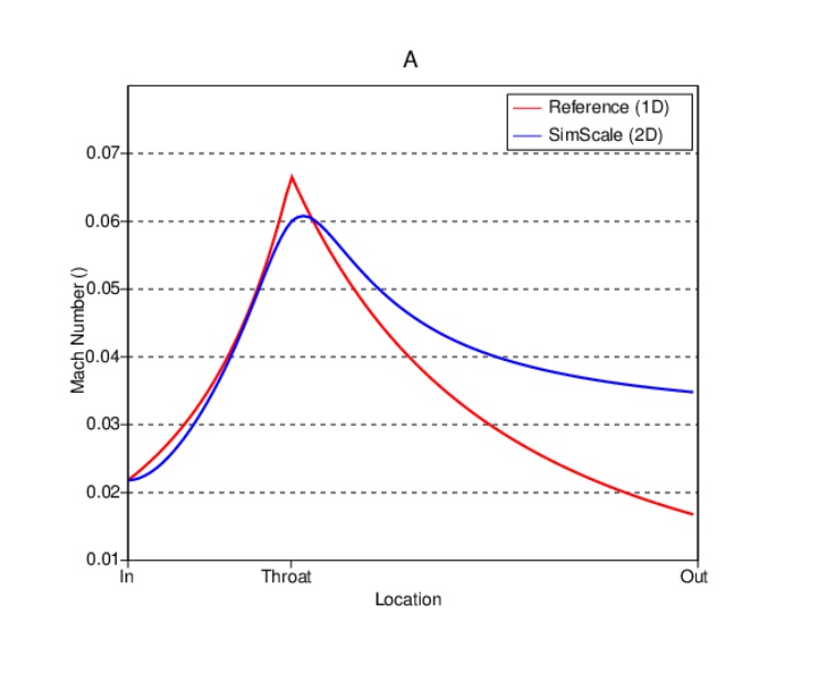
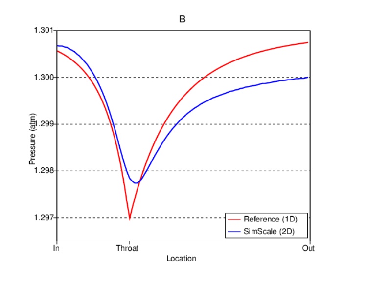
I’m doing an university project about turbofan engines. I wanted to obtain some graphs comparing the simulation results with the mathematical results I have.
The Mach no at the nozzle exit should be around 1 but there should be also an external expansion. Therefore after the nozzle there should be an higher M.
Since you already run the simulation with zero-gradient b.c.: are results somehow acceptable respect to the expected value? If so, I can stick with it… I didn’t expected such a hard simulation!
Ah. I assumed you wanted to determine the turbulence intensity factor at the outlet of the nozzle. Hence why I was asking for the goal. Determining that is much much more complex and RANS is not accurate enough as it tends to under predict.
So since now you have made your objective clear, I think I know how to proceed. But first, you will need to make some geometry changes which may be a little complicated.
First, you need to simplify your geometry so that we can run a slice of it rather than say, a quarter. Referto Jousef’s post on the Laval Nozzle Simulation.
Secondly, we need to take the model and mesh it in 2D. That will greatly reduce simulation time and resources as well as allowing us to refine the model to a high degree without incurring too much computational cost. This is a little complex as SimScale cannot mesh 2D but there is a workaround. Let us get to that after you’ve done the first step.
Lastly, we need to determine the boundary conditions. Seeing as your flow rate is sub-sonic, but compressible, I believe we can continue to use a pressure based solver. However, they tend to be not so cooperative and I have minimal experience with getting them to work properly, so we’ll figure it out when it comes.
No, not at all. As mentioned earlier, my assumption as to what you wanted to determine was wrong. As such, my runs are already invalid.
Yes that is the problem with this kind of compressible flow simulation. Would help if I was more familiar with the math but oh well. Lets see what we can do.
I tried to mesh the “slice-geometry” before but snappy didn’t mesh correctly the lower thin part (see the lower part of Mesh 4 from geometry “nozzle2”). Probably I’m missing something but I think this type of geometry works if generated with blockMesh.
Anyway I uploaded another time a sliced geometry “nozzle_slice”. Though I don’t know what to do in order to mesh smoothly.
I’m guessing we will use the “empty” bc right? If this is the case I also uploaded an “extruded” geometry (“nozzle_extruded”) that should work as well. I didn’t want to change what you were planning but I wanted to try something since I don’t know how to mesh correctly the sliced geometry. As you can see, the mesh generated with the extruded geometry is bad as well.
So, I am waiting for your help! Let me express my gratitude again: your help is huge!
Yes this works, but we need to perform a 2D extrusion with OpenFOAM. Refer to this post. I could do the extrusion for you, but again, it will take awhile. I suggest going ahead and attempting this and I can reply on the issues you will encounter. Good chance to use OpenFOAM i guess .