Hi @simonbbaker,
thanks for reporting the question. As @jousefm mentioned. there is currently no straight-forward way of getting the parts which are unconnected, but we have two features in the pipeline which would improve this.
For now I see in general two possibilities, which boil down to the same principle: loosen up numerics and force the solver to compute a result, looking at the results will tell which parts are unconstrained and have a large displacement.
I made a copy of your project and applied both versions (one with a static and another with a dynamic analysis). You can check out the results here: Project link not available anymore
Before doing anything, I also imprinted your geometry using a geometry operation available from the geometry context menu. This will in general improve the accuracy and success probability of the automatic contact definition.
For the static analysis I did the following:
- add a sample fixture condition
- enable gravity in order to have a load on every part
- add a small elastic support to all surfaces
- loosen up the numerics (disable “Precision singularity detection” by setting it to -1, disable “Stop if singular”, disable “Linear system relative residual” by setting to -1).
For the dynamic analysis no elastic supports were needed and the “Geometric behavior” in the model settings were set to linear to increase solve speed and robustness.
Here you see the resulting displacements:
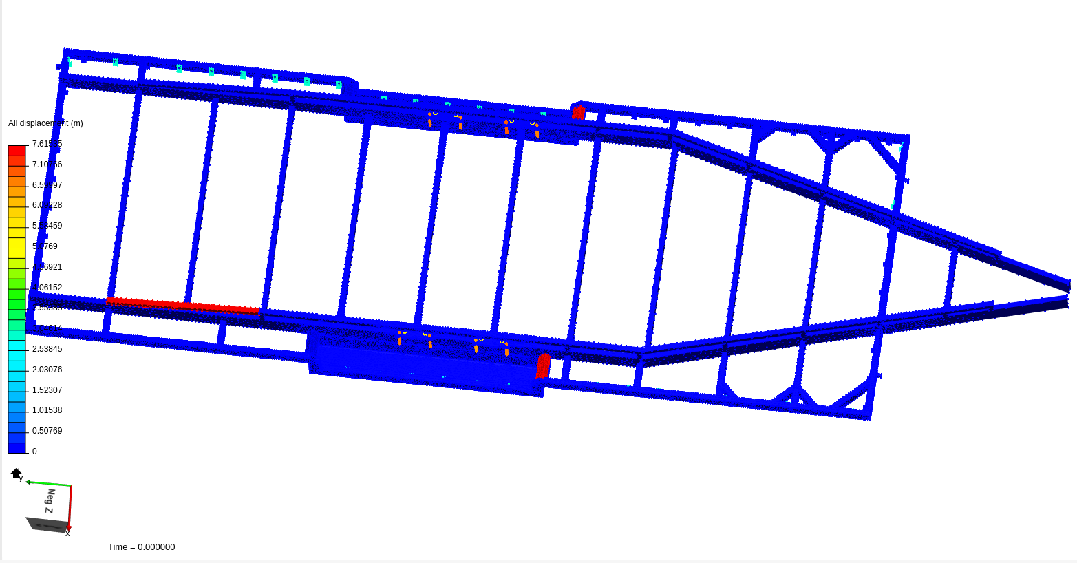
Static Analysis displacements
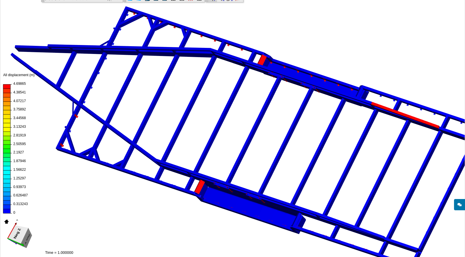
Dynamic Analysis displacements
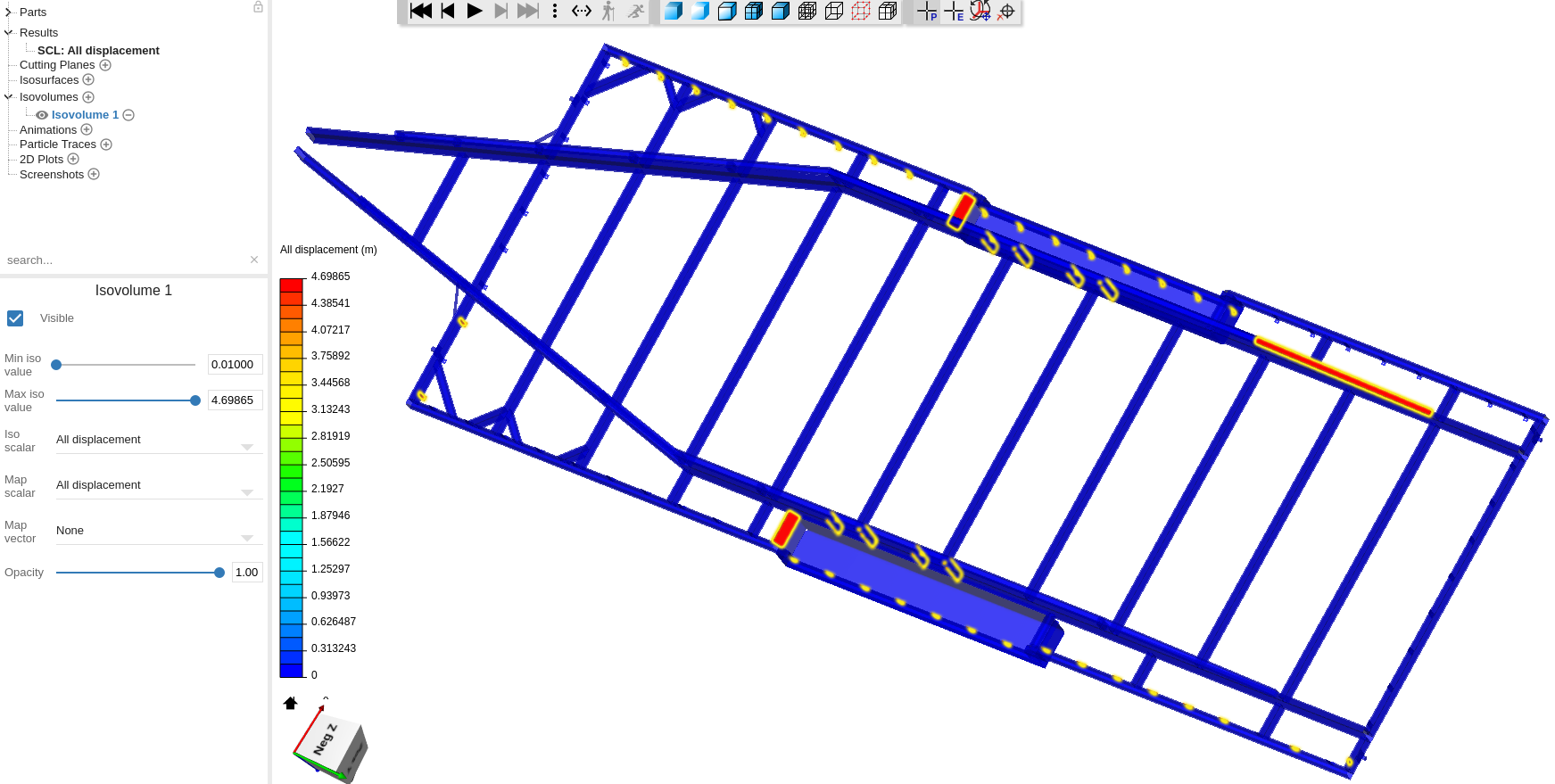
You can add an iso-volume visualization to better spot also small unconnected parts:
I know that this is not really an ideall solution, but it could at least serve as a work-around until we have released a better solution.
Let me know if there is still sth. unclear.
Best,
Richard