Newbie. Forces and moments Help

Hi,
I know I can measure down force of a car using Result control / forces and moments but I have two questions.

  1. Are the results in a specific unit of measurement or are they just a numerical value for comparison?
  2. Is it possible to measure the amount of down force on each of the four wheels individually ?

Thanks in advance

Hi Ged,

I’ll add @yosukegb4 and @pfernandez to this one, I think they can help you out.

Best,
Anna

1 Like

Hi Ged,

In incompressible flow the Navier Stokes are divided by the density so you end up with kinematic units (kinematic pressure, kinematic viscosity, etc.). If I’m not wrong, even though you can define a density, OpenFOAM will default its value to 1 when in incompressible. I usually stick to coefficients and then calculate the forces using the well known equations.

Regarding your second question, there’s no direct way to do that in OpenFOAM that I’m aware of. You can use bins to get the distribution of forces and then, with a static analysis, calculate the forces exerted on the front and rear wheels as in this project

2 Likes

OK I understand thank you for your help

1 Like

Hi @gcanfield,

I also think it is the best way to calculate the forces of car from the coefficients.
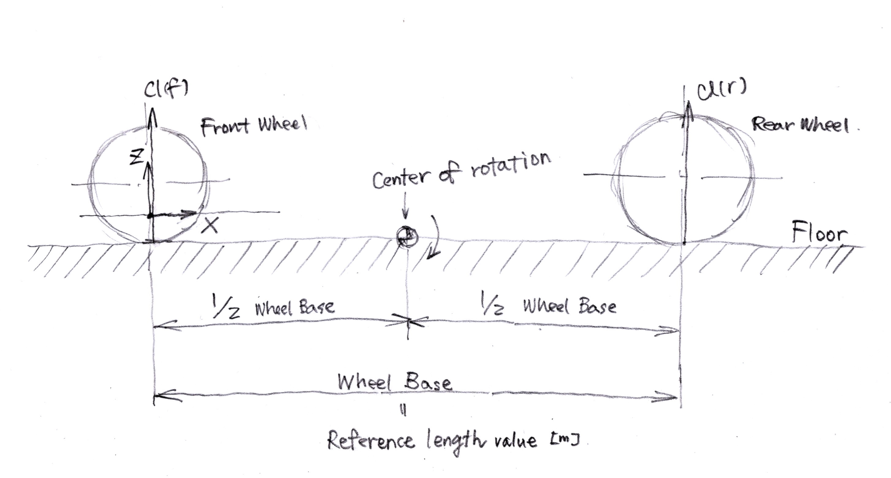
These coefficients are distributed to the front Cl(f) and rear Cl(r), not to each wheels.

I calculated the coefficeints in the setting as in the figure below.

I do not have conclusive evidence of the setting because it was judged only by myself, but I was determined that they are probable from the following points.

  • The coefficients calculated in Result Control matched the coefficients calculated manually using forces in Result Control.
  • Manual calculation formula was the same as the one that is written in the code. OpenFOAM-2.1.x/forceCoeffs.C at master · OpenFOAM/OpenFOAM-2.1.x · GitHub
  • When I removed the rear wing that is almost above the rear axle, the reduction of Cl and that of Cl(r) was almost the same without change of Cl(f).

Trials and errors of these settings remain in the following simulations.

I would like someone to confirm wheather the setting is correct or not.

Anyway, I hope this post helps @gcanfield.

Best,
Yosuke Yamamoto

1 Like

Hi yosukegb4
Thank you I can understand better now the settings in Simscale.

My problem is I am working with Racing Sidecars and they only have 3 wheels all on different tracks.
This is why I was asking if it was possible to measure the wheels individually.

Thanks anyway

Hi @gcanfield,

you can create multiple result control items within SimScale and assign them to an arbitrary set of faces. So in your case, you could simply create 3 result control items of the type “Forces and Moments” and assign each one of them to an individual wheel. That way you’ll get the 3 forces separately.

There are also ways to do this retrospectively in Paraview but they will be a bit more elaborate.

Hope that helps,

David

1 Like

Hi David,

Thank You I will try some experiments using this method.

1 Like

Hi David
I have tried what you suggested but it does not work. the force is the same on each wheel no matter where you fix a wing to the model.
A question about settings for Drag coefficient.
I take it that Reference area is the frontal area of the model but what is Reference length?
Also for pitch axis does this need to be set to the center of the model or is it just set to one of the 3 appropriate plans?
and how about center of rotation I can find nothing in any tutorials about these settings

Thanks in advance.

Hi @gcanfield,

is it public project? Could you post the link here then I’ll take a look. The forces and moments result control item computes drag & lift only for the faces assigned to it. Could be that the forces are very similar though.

Best,

David

Can confirm yosukegb4’s method, although some of my mates take the sum of moments at the contact patch of the rear wheel just because they can. It doesnt matter where you take the sum as long as you are consistent with the coordinate system you defined - positive vector and moment directions etc.

If you look deeper, centre of pressure is not a point. It is either a line or a plane.

Best.

P.S. people like to put the moment point ( or locate CoP ) on the ground just because that’s where the grip is ( where wheels in touch with the ground )

1 Like

Hi David,

I have made a simple 4 wheel model to demonstrate.
I have created multiple result control sets for front and rear wheels but the results are the same for front and rear.
It only measures the forces on the wheels and nothing connected to them?

Ged

Hi dylan,
I am very new to CFD and could not really confirm yosukegb4’s method.
Thanks for your tips with the settings although im still not sure what I should be putting in for reference area?

Best

It doesnt matter what reference area is set. You only need a consistent number throughout the computation to make comparisons. But, if you want to compare your design to something else, and you happen to know the reference area used by its designer, you can set yours to the same number. The output coefficients will tell you how the two designs compare. I usually cant be bothered so I just set it to one.

3 Likes

Hi dylan,
Thank you very much, that’s all I wanted a simple answer :slight_smile:

Hello, how would it be possible to get the distribution of forces? Are there any softwares to do such thing? Or does it involve some OpenFoam tool?