I ran a Magnus Effect simulation, basically a rotating cylinder in a steady wind. I need a little help understanding the results. I am trying to calibrate the result against simply ideal force for my cylinder rotation and wind speed. For the diameter 0.089m, the wind speed of 25 m/s and the rotation of 3000 rpm (314 rad/s) and length of 0.5m I should get an upward force of about 240N but I get only 24N. Here is my project directory. Run 2 is the latest.
A few questions and thoughts I have are;
The force plots give N or Nm. How can I tell which it is?
I think I correctly selected the surface to compute the force on, the cylinder.
I am not so concerned with edge effects right now and would like suggestions as to how to efficiently make it a simulation if an infinite cylinder to reduce computation.
I just want to match basic theory before I experiment with details and changes.
Tagging the @cfd_squad here first of all. First thoughts what could have gone wrong:
Scaling?
Why is your cylinder touching the boundary face? Try enclosing the whole cylinder and instead of rotating the cylinder enclosing it in another cylinder with enough diameter using the MRF approach? Not sure if that is the optimal way to do it but it would be worth a try
Result Control definition might be defined in a wrong way giving you weird force results - would have to check.
Let me know what you think and also awaiting some additional input from my knowledgable PowerUser colleagues
Thanks. The edge where the cylinder hit the wall is a symmetry boundary. I used half the length. I am not sure what you mean by scaling. The drawing is in inches from Onshape but it looks correct against the meter stick in Simscale. I was hoping to use a simple rotating cylinder in air rather than complex rotating zones. I can see that a more sophisticated setup would be more accurate but I am off by a factor of ten. That tells me there is something fundamentally wrong in my setup.
@Robert01: Jousef is right. You cannot use ‘rotating wall’ BC for that study. You should use MRF approach, which means you define that bigger cylinder around your solid cylinder. MRF zone should not extend too much into simulation domain. In my Magnus effect studies (you can find in old projects) I used 5-10 % bigger diameter only to have that MRF zone defined.
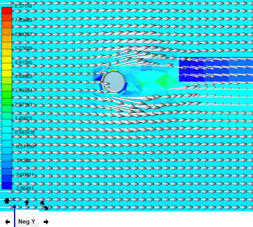
In you second simulation you can see that there is near no lateral force created by your rotating cylinder.
Thank you very much Retsam! I’ll try the MRF approach. I assume the rotation of the MRF matches the rotation of the cylinder, which in my case is 3000 rpm (314 rad/sec).
Is there one of the study simulations you recommend in particular?
You use slices in some of the simulations. Is that basically a quasi 2D approach? Do you recommend that?
I’m still confused about how to read the force plots. Is it always Newtons or is it Newton-meters? Why does the force plot axis say N or N m?
Yes, MRF rotation speed should be those 314 rad/sec.
I suggest you study first 10 simulations
Yes, I used quasi 2D approach, as it allows to reproduce theoretical results (to some extend, for infinite length cylinder). You can see also, that it is necessary to use BL (boundary layer) and estimate y+ depending on rotation speed (well, tangent speed of fluid in m/sec).
It is in Newtons, those force plots. It should be in Newtons, anyway. I do not know why plot is using Nm…
Thanks. I’m really trying but this is not at all easy! I’ve tried to set up a MRF zone by adding a volume around my cylinder in Onshape but I cannot get that volume selected in the MRF interface no matter what I do. It only wants to select the whole flow volume and nothing else.
Please do not use Enclosure provided as an operation in SimScale.
In OnShape, use boolean operation to get your Flow volume (simulation domain): from a cube you create around your cylinder, you remove that cylinder. Results is the new volume, being that cube without the cylinder (so called simulation domain, just the air around your cylinder).
Do a new assembly composed of that new solid and a second solid, a bit bigger cylinder, which will become your MRF zone.
Import that assembly to SimScale. You should have two solides. One will be the simulation domain, second, MRF zone containing that void space (your cylinder).
Wen preparing the mesh, do not forget to use ‘Cell zones’ and point to your MRF volume (this is a new version of SimScale and possibly you did not notice that my previous simulation was not having that way of defining the MRF zones).
I admit it is not obvious, but once you understand how it works, you prepare everything in OnShape and you do not need to mess with geometry operations in SimScale.
Yes, energy can have many forms but the article you cite says that “Newton-metres and joules are dimensionally equivalent in the sense that they have the same expression in SI base units, but are distinguished to avoid misunderstandings when a torque is mistaken for an energy or vice versa.”
In our case XYZ Nm moments/torques are needed in addition to XYZ forces to apply to our objects of interest in order to maintain the steady state that we are investigating in our ‘steady state’ simulations.
Thanks. I looked at these. It looks to me that the forces are much lower than I expected by a factor of 5-10X. Are these runs calibrated to data? I also tried the method of creating the MRF zone in Onshape. Still can’t get Simscale to run as it gives me errors about analysis types and zones.
A multi-region mesh was assigned - this analysis-type requires a single-region mesh.
It may be that my MRF and other zone (part 1) are two separate non-overlapping solids from Onshape. But when they intersected before I also got an error.
I tried to build my confidence in CFD simulations by running the simplest case I could think of, a flat plate 90 degrees to the wind. At least that seems to work alright.
There are many examples of full 3D and quasi 2D rotating cylinders set-ups. Results are matching experimental ‘to some extend’ and only partly matching theoretical ones (rotation speed / wind velocity are essential).
Cheers,
Retsam
P.S. [Magnus 3 simulation] Your MRF volume should be, in that case, a full cylinder. Your Simulation domain (Part1) should be just a volume (of air), your rotating cylinder being removed. So you volume of air has a void inside in a shape of the rotating cylinder.
Thanks. I have been studying your work. It would then be convenient to be able to pick the surface of the domain as the place to measure the forces on but for some reason Simscale won’t let me pick that surface. It only lets me pick the outer surfaces. However, using Newton’s Third law I am using the walls to compute the force on the cylinder since they must be equal but opposite. It seems to work.