The model is the actual air volume inside the fan duct.
I tried to build an enclosure using simscale, but I end up with a volume from which my duct gets substracted and I have no face to apply the initial boundary rule (inlet). If I check “keep parts”, I end up with multiple volumes and the software won’t run…
Basically, I am still trying to understand the logic of Simscale, because most of my work is guessing and getting excited when it gets right, without knowing what I did.
What I want to achieve is to see how the air stream will behave inside the tube and once it exited (if it blows in the correct area in relation with the hotend).
I’d appreciate some help and explanation of how and why…
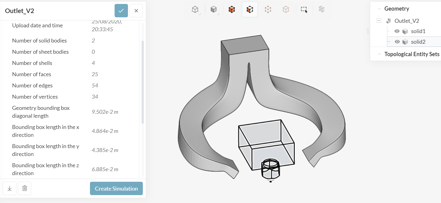
Which one is the ‘actual air volume’, please? Solid1 looks like a duct. If it is the case, you should have a geometry with only that solid… In that case you would not need an enclosure, as mesh will be created inside your duct…
@Retsam
I was planning to use the “enclosure” feature in Simscale to create my surrounding air environment.
Solid1 is the interior of my duct, the air volume, if you wish of the duct, not the duct itself (not the walls of the duct).
For now I am trying to focus on the path the air is taking, not the outer shape of the fan duct (eg. the walls).
Is it possible to use this geometry to simulate? If yes, what are the steps necessary to produce a valid enclosed flow region?
So this is your ‘simulation domain’, in other words, the air volume. Again, your simulation should be done on the air volume, not on duct. So far, so good.
Import only Solid1 volume (air, if you wish, from inside your duct).
Mesh it (you can start even with Standard mesh).
Define velocity inlet and pressure outlets.
Run first simulation: observe results, remesh, resimulate…