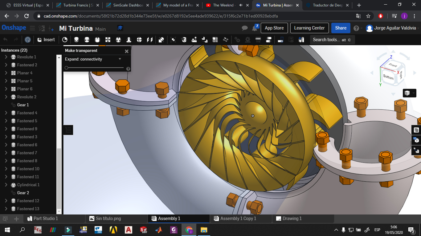
Hi, I need help with my project. I want to simulate the flow of water through a Francis turbine but I don’t know how to extract the internal volume correctly, I have reviewed the cad I made and I don’t find any gaps as recommended by the simscale tutorials (I think). I want to repeat the simulation for different angles of the guide vanes but I can’t even extract the volume of the fluid. Please if someone could help me I would be very grateful. Thank you
this is the link of my project:
Hi @jaguilarh!
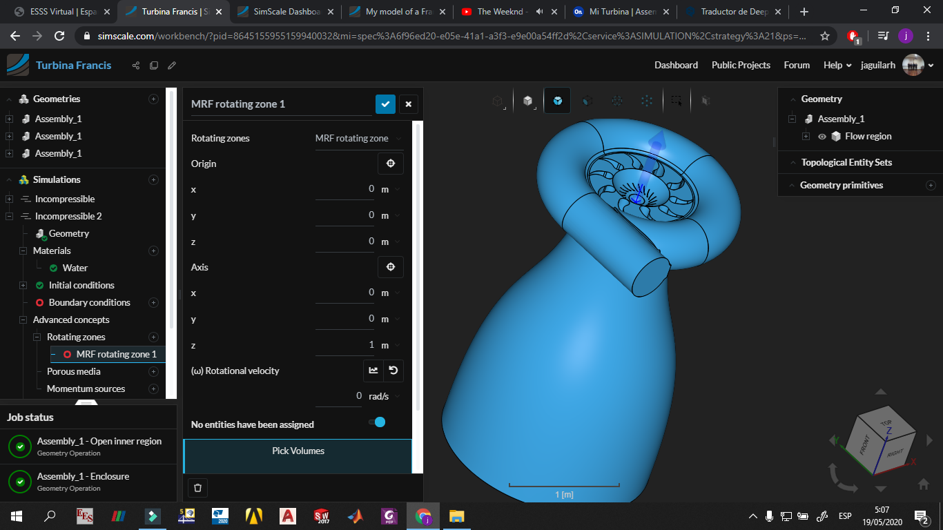
There are some good projects in the public projects section, like that one: SimScale - however if you want to make the blades rotate you would need an additional zone to apply MRF on it. Also your model seems to need further de-featuring as there are parts outside of the turbine that have no influence whatsoever on the internal flow.
Once that is fixed we can have a closer look on the volume creation.
All the best!
Jousef
1 Like
Hey @jaguilarh,
There’s a centrifugal pump tutorial that shows the exact process to prepare the geometry in your CAD software. There you go: Fluid Flow Through Centrifugal Pump | Tutorial | Simscale
Basically the steps are described here:
PS: there’s a francis turbine tutorial coming out soon-ish, so stay tuned!
1 Like
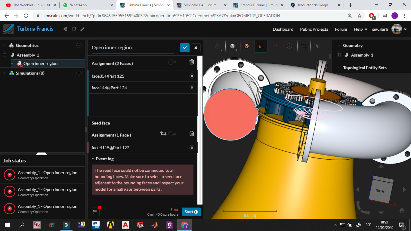
hello again and thank you for your advice. I have already been able to extract the volume of fluid, the solution in my case was to choose the seed side well. Well, as recommended, I was looking at the project on the centrifugal pump but I don’t understand the part about how to build the rotary zone. That is done here at Simscale or on another cad platform like onshape (which I used for this project).
If so, how do I do it? It tells me to create a solid that wraps around the rotary zone, but if I do that, it will cover the regions between the blades. I think you should import two different geometries: one the volume of the fluid and the other the rotating zone, but I don’t know how to do it and the tutorials are very short and specific.