I am trying to run a simulation on Oscillating Water Column, basically a device that has an opening in its submerged part that connects an inner free surface to the external environment. I was able to set the simulation for its decay (inner water level slightly higher than outside as initial condition) properly using the multiphase flow ( look for “Oscillating water column - decay” in public projects , SimScale), and it seems pretty reasonable, but I wanted to measure the free surface elevation at some points.
The only way I managed to do it was by creating an array of probe points vertically distributed and by evaluating the phase at each try to interpolate to find the free surface as the cell in which alpha = 0.5, but this is both laborous and innacurate. Does any body know about any other way of measuring the free surface displacement? I am a begginer in cfd, but I’ve seen people setting a ‘wave gauge’ at the desired locations, which seems to be way more accurate.
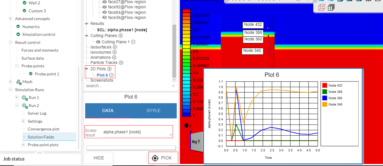
First I created a cutting plane in the mid section to give me a clear vision of the water level; then I created a 2D plot to analyze alpha phase 1 [node]. Then simply click on nodes of interest (I could only select those in the walls).
Is there a better way to do this in paraview? Maybe a plot over line? @DaleKramer
I am curious why you are only interested in elevations at some points (I assume you mean ‘at some points over time’)?
I would think you may want to have a look at say, the difference in the elevation of the average alpha=0.5 level in the ‘inside’ vs the ‘outside’ over time… Or something like that… (This is more challenging but I think it is possible to do with ParaView)
What I want to get is a time series of the free surface position, something like a vector as a function of time (eta(t)), basically to see how the inner free surface decays in time. We have experimental data in our lab for this very case, a wave gauge placed at the very center of the cylinder, and I wanted to validate this simulation (part of an introductory level course on cfd).
Ideally I’d be interested in having the entire free surface location for each timestep, like a cloud of points for each instant (z(x,y,t)), but I assume this might be computational costly so I am focusing on specific locations (such as the center of the cylinder) that I can validate. The elevation outside the OWC, at least now, is not so important (I will probably have to check the domain size, but this is in the future). Any approach based on the frames is not the ideal due to the small number of frames or large size of the files I’d get. The decay period is close to 0.5 s, therefore I need a ‘sampling’ frequency of at least 10 Hz to minimally capture the cicle properly. Furthermore, I need something I can handle externally, like in matlab, so I can treat the data. That’s why I am focusing on some of the Result Control tools, because I can download the csv file corresponding to it.
Besides this attempt of using the alpha, which is not working very well until now, I thought of using what I assume to be the hydrostatic pressure (p_rgh) or the vertical velocity (Uz) in the points, but neither is working well to me yet, the former because p_rgh is larger in shallower points, which doesn’t make sense to me, and the later because the integration of the signal is the ideal approach.
Thanks @Ricardopg. This seems nice, but it is limited to the frames SimScale provides me. I need the time series with a ‘sampling frequency’ significantly larger than the frame rate SimScale generates. That’s why I was focusing on the Result Control feature.
So, now we know why you ask for point, because you have experimental data for the center point (which likely drops faster than the non center points on the ‘inside’ region.
I am jumping my response to answer this next… I do not think you will be satisfied using Results Control tools here. I suggest you start downloading the full sim rum results and examine them in ParaView where almost anything is possible.
You can add filters that perform calculations and integrate the output parameters in unimaginable ways on many extracted subsets (cells,/faces/points over many more types of slices, isovolunes, area of a slice etc) of the complete data set.
I think this could be done in ParaView.
But all these would be based on the time steps of your sim (I think you use ‘frames’)…
Why can’t you run a sim run with many times steps in 0.5s?
The timestep I’m using for the simulation is 5 miliseconds, but it does not allow me to write all fields for every timestep, would be extremely large. What I’m refering to as frames is the timesteps in which the fields were written by the software, which is related to the animations I can create.
For instance, for a 5 seconds simulation it provided me only 12 frames, which means I have data for the entire field at a timestep of about 0.25 s, which is really bad to me because is half the cycle I want to capture. For a simulation of 1 s it recorded 17 frames, but this allowed me to have the fields for timesteps of about 0.05 s, way better!
I downloaded the field and checked out Paraview , I didn’t know it so thanks for the tip! I managed to create a few interesting fielters and it does allow me to create some ‘wave gauge’ by creating lines and checking the alpha along it. However I am still limited to the timesteps that I can get the fields written, the frames I mentioned. I will run the cases with less simulation time so that I can have the data at a reasonable ‘sampling rate’, and alternatively try something with the Result Control since this approach would allow me to run longer simulations and have the time at small timesteps.
Thanks a lot for the suggestions and, if I find some alternative way I will update it here!
In steady state CFD I always write results every iteration, are you sure you are so limited. (I have not done any multiphase so maybe a multiphase person can help here, I just assume that in the full solution set, you would get all parameter values for each iteration (this multiphase seems to behave like a transient CFD sim run) ) …
You can also tweak “Write interval” in simulation control. It’s basically the frequency at which the data sets are saved. E.g. if write interval is 50, a data set will be saved after every 50 steps.
Naturally the number of sets that you can write is going to be limited by the machine’s memory.