Hi,
I have simulated a multiphase case of a AUV model successfully. I am interested in studying the effects of drag and lift on the vehicle but when I check the output values, they are insane of the order e138 !! Would love to have someone look at my project and give me some pointers to get reasonable force outputs.
Thanks and regards,
Cecil
Project link - [Deleted by author]
I think it must because the domain size is not big enough. Will try running a sim with a bigger domain.
Hi @cecil_pabbathi!
Please let us know how things are going.
Cheers!
Jousef
Hi @jousef,
I have imported a model with some surface splits to define inlet separately for water and air. I made sure the mesh box is exactly the same size as of my external domain but after the mesh is completed, the surface splits are lost. How do I proceed ?
Regards,
cecil
Hi @cecil_pabbathi!
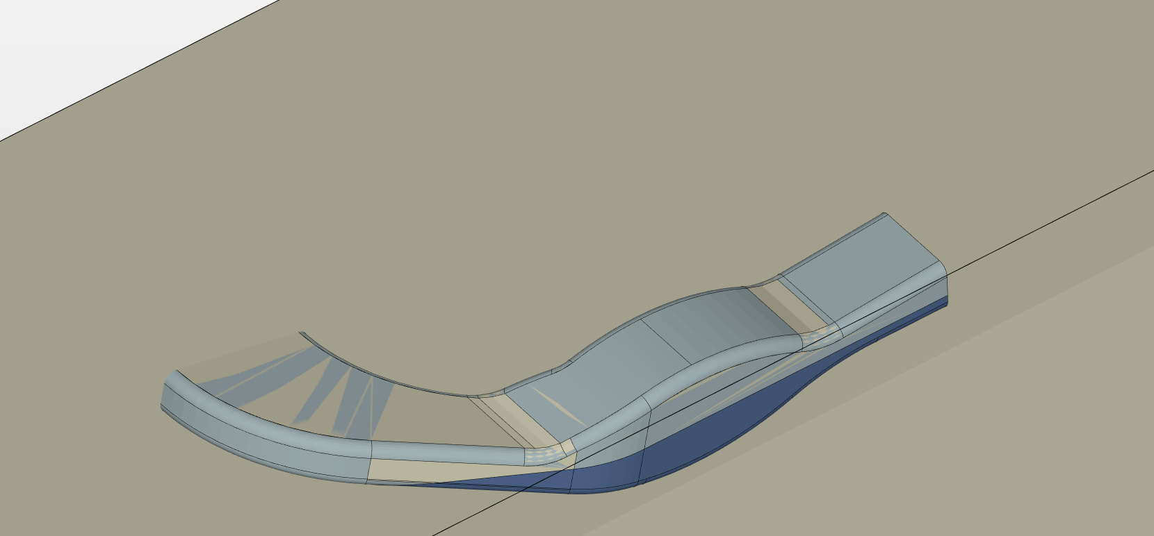
What I have seen from your setup is that you want to perform a 6-DOF simulation, is that correct? In any case make sure that your geometry is clean and that there are no overlapping surfaces (see attached photo).
P.S.: As an example you may have a look at the simulation from my colleague @Ali_Arafat: [6-DOF Simulation of a Boat]
Cheers!
Jousef
Hi @jousefm,
Yes! A 6 dof simulation is what i am trying to simulate. Thanks for the quick reply. Will correct my model and let you know how it goes. Cheers
Hi @jousefm,
Thanks to you I was able to set up my sim properly but unfortunately I run into this error “The Courant number (CFL) exceeded the limit of 1. You may experience either instability or bad temporal accuracy. It is recommended to keep the CFL number below 0.7. In order to achieve this you need to decrease the time step”. I know this number relates the mesh size with the time step length, I have used a time step length of 0.0005. How do I calculate the correct time step length in my case ? Cheers
Hi @cecil_pabbathi!
You can have a look at the solver log for instance and adapt the time step so that it is approximately 0.5. Does that make sense?
All the best!
Jousef
Hi @jousefm,
Sorry mate. The solver log doesnt make sense to me. Would you mind elaborating a little more ? Thanks !
Hi @cecil_pabbathi!
Will get back to you as soon as I am at home and had a look at the progress you made.
Cheers!
Jousef
Hi @jousefm,
Thanks ! Really appreciate it. Take your time.
Hi again @cecil_pabbathi!
I need to investigate this a bit more as the solver log unfortunately does not give the CFL number at this state of the simulation. Would get back to you as soon as I have created a successful run if that is okay. If you manage to fix the problem by yourself in the meantime, please let me know.
Best,
Jousef
Hi @jousefm
Thanks again ! Really need to get this case up and running. Out of curiosity, has the automatic timestep option been scrubbed altogether ?
Hi @cecil_pabbathi,
Not an expert on multi-phase DOF simulation but it seems like the issue you’re encountering are a result of a setup that still has issues rather than say a non ideal CFL number that causes your simulation to go into instability instantly.
Referring back to what Jousef referenced with regards to the 6DOF boat project, there are some irregularities that are in your simulation as compared to that.
For a start, your phase fraction sub-domain is being applied to a small area rather than the entire water domain which is occupied. This is what the 6DOF boat simulation project has done. You can start with that change and see if it helps.
The second irregularity I noticed was the boundary condition related to the object in the water, which is this case is your geometry. In the 6DOF boat simulation the geometry is defined as a moving wall velocity with zero values in the xyz direction, fixed flux pressure and a phase fraction value of gradient set to zero. Yours is a fixed value. Maybe this change might help.
Generally speaking if you’re running into issues like this I don’t think it is a CFL number issue. I would recommend looking into a successful simulation like the 6DOF boat project and to replicate it as closely as you can to every detail. Of course your case I believe is slightly different due the presence of the inlets having a set velocity so adjust as accordingly.
Hopefully this helps! Do let me know if it works.
Cheers.
Regards,
Barry
Hi @Get_Barried @jousefm ,
This was blatant ignorance from my side. Earlier I had set up a case with a smaller domain and the case ran well but I wasn’t happy with my force plots. I uploaded a newer model with bigger domains but I didn’t want to go through the pain of setting up my case again so I made a duplicate of my case set up and hence the water domain remained small. Sorry for the trouble I put you guys through but thanks again. 
As for the geometry being set up as moving wall velocity, I definitely have plans to study 6 DOF movement of the body under the influence of waves but at a later stage perhaps. For now, I am interested in the drag forces alone and optimizing the geometry accordingly.
Cheers,
Cecil
Hi @Get_Barried,
Coming out the CFL error, now I run into Fatal I/O error  . I am using this project SimScale as reference because I feel it closely resembles what I want to study as well.
Hi @cecil_pabbathi,
I think I figured out the problem! So all you have to do is to set your outlet mean velocity to a positive value, which in your case is 3m/s. The negative value of the outlet means flow is somehow stuck and flowing back in through the outlet. I’ve copied your project over and it seems to be running fine so do try this and let me know.
Cheers.
Regards,
Barry
2 Likes
Hi @Get_Barried,
You’re a lifesaver ! Thanks mate. The simulation runs now. When using the other project as reference, it had a backflow outlet velocity defined as well. Really appreciate your time & valuable inputs. Cheers !
Regards,
Cecil
1 Like
Hi @Get_Barried @jousefm ,
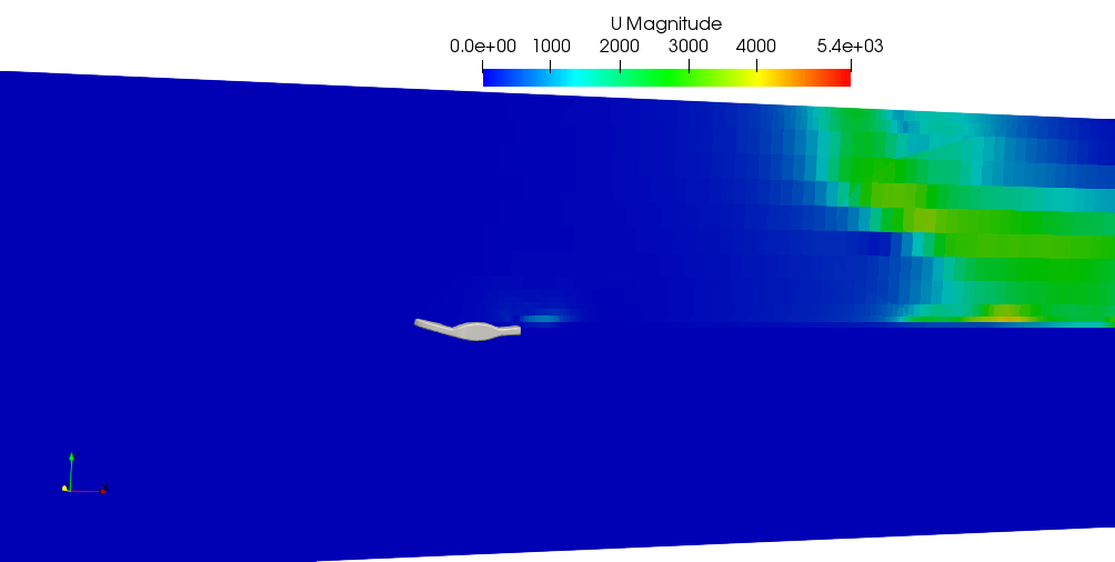
So I ran few simulations successfully. When I looked at the velocity contours, the velocity remains zero throughout(20 timesteps) without really changing much which makes no sense because an inlet velocity of 3 m/s was defined. Also had a look at a similar project (Development of Wakes Behind a Boat with CFD Simulation by sjoshi | SimScale), the outlet mean velocity here is also defined in the opposite direction of the inlet velocity. Could that be the reason ? Would love to hear your thoughts. Cheers.
Regards,
Cecil
Hi @cecil_pabbathi,
Looking at your force plots for 20s, you will realize that something is seriously wrong. You’re getting moments of over 10k which means something went wrong somewhere. What the exact issue is I’m not too sure but the current simulation you are running (5s) is going well and checking the force plots you do have rather nominal values that should give out what you’re looking for.
Let it finish running and we’ll work from there.
Cheers.
Regards,
Barry