The residuals for your last run look much smoother which not necessarily has to mean that the solution will be accurate or “correct” but looks much more promising than the last run (20sec) that you have created. Let’s see what we can derive from the post-processing.
Hi @jousefm@ @Get_Barried
I took a short break from work so could not spend much time on the project either. The simulations ran well although I might need to decrease my end time length and increase my time step a bit to get more accurate results. I have a couple of questions as I am fairly new to transient and multiphase simulations.
Regarding the drag & lift, I want to specifically calculate how much drag is induced by water and likewise air. So i have split my CAD model into two parts, one part which will be immersed in water and the other exposed to air. So if I calculate the coefficients for both these parts and add them up it should give me a measure of the total drag & lift on the body, right ?
I have attached a short animation of my simulations. What you see is an isosurface of water phase at 0.5 colored by velocity magnitude. Towards the end of the simulation, there is a backflow phenomenon like water hitting against a wall, is that normal with the outlet bc I defined ?
Don’t worry, I’m even newer We’ll learn and solve along the way.
While you may be able to supposedly get the values out. I do not think that individually calculating both values and adding them up will give you a proper representation of the drag and lift on the body. This is due to (referring to the animation) water and air both “mixing” together and its very difficult to quantify exactly the lift and drag forces due to each medium. Fortunately, there is no need to do that. You can simply just obtain results directly from the body regardless of water or air and produce a lift and drag force value out. However, due to the nature of the results right now, this also may not accurate which brings me nicely to my next point which you already have kind of identified.
I suspect your outlet seems to be “blocking” the flow of water, hence the presence of a “back wave” occurs which will significantly affect your results. If the water were to instead “flow normally” per say and no backflow occurs then you can obtain direct results of lift and drag directly. As for how to fix this issue I am not exactly sure how. On one hand increasing the outlet velocity is one way, but referring to the sample case, the flow doesn’t behave like this despite the same outlet conditions. The backflow likely occurred due to the very strange sudden flow speed increase at around the 7s which is very strange. I suggest maybe increasing the area of the bounding box significantly to mitigate the effects of the wall and if this still continues, we’ll probably have to look into the side wall conditions.
Thanks again for your valuable input mate. Trust me I am learning a lot from you along the way I will try a simulation with a bigger domain and see how that works out. Cheers.
Help ! I tried setting up a new sim with a bigger domain using the same boundary conditions but I keep getting plagued with the CFL error Here is the link to my project [Deleted by author]
HI @cecil_pabbathi, have you tried aligning your numeric with the example project you have linked? I would try reducing the courant number (alpha and normal co). Also the mesh for the example is much less locally refined. I found when I was doing my slosh analysis (although this was real transient not locally sidestepped) if I had excessive local refinements, the fluid passing into the refined cells would cause courant numbers to rapidly increase and cause divergence.
The animation above looks like the solution just became unstable and produced non physical results, Trying to ‘fix’ the outlet might not be necessary.
Your post was definitely informative and I coarsened my mesh like you said but still I have trouble getting the simulation to run. The simulation crashes as soon as it starts so the solver log isnt really helping either.
Hi @cecil_pabbathi, mixed report. I know what the problem is but haven’t had success at the moment in fixing the issue, I hope I might have some time to look later but here is the issue:
Interesting. I have some findings to share as well, Earlier today, I changed my outlet to a pressure outlet and the simulation runs though I get non physical results but still there seems to be a problem with domain initialization like you mentioned. Maybe a different type of outlet condition needs to be defined for my case ? Thanks for looking into my project. Really appreciate it. Cheers.
While Darren works on fixing the issue, just a quick comment. You should increase the Cartesian box for the water phase (you labelled it “WaterLevel” in your “LatestRuns” simulation) in the positive Y direction a little so that you don’t risk not defining the supposed area of where water should be.
Don’t think this will fix it at all but just to remove any possible problems.
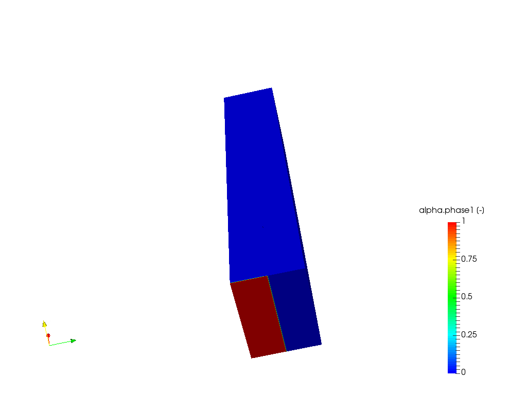
Have a small problem, I am trying to set up a new case with some changes to my geometry to see if it helps me get unstuck. As I need to define two inlet phases, I have my surface splits set up accordingly on my outer domain but after meshing, my inlet faces alone are merged. Look under ‘ForCFD Mesh’ in my project.
Yes. Apparently it does not seem to work. I tried using all available formats that simscale supports but still it the problem remains. The surface splits are captured on the side walls of the domain but not the inlet. Cheers.
thank you guys very much for all your help, i found it very useful. i was just wondering if i can ask quesitons in case i would have some as i’m new here. thanks!
This is very strange. Unfortunately I don’t have much experience with this issue so I’ll leave it to the rest to see what they can do. I will take sometime to try it out however.
 I will try a simulation with a bigger domain and see how that works out. Cheers.